WireGuard Connection Wizard
We just rolled out a brand new tool to help you set up working WireGuard connections: we call it the “Connection Wizard”. If you don’t know how to get started with WireGuard, the Connection Wizard can help you get started. Plus, it makes it easy to add new connections to existing WireGuard networks.
This article will demonstrate how to use it to set up new WireGuard connections under two scenarios:
-
For the first scenario, we’ll set up a New Point-to-Site WireGuard Network from scratch to allow remote access to a cloud site from a couple of end-user workstations.
-
For the second scenario, we’ll add to an Existing Point-to-Point WireGuard Network to create a new connection between two servers that we had previously configured with Pro Custodibus.
New Point-to-Site WireGuard Network
For our first scenario, we’ll set up a point-to-site WireGuard network, allowing two different user workstations to remotely access the private servers at some cloud site. These are the steps we’ll follow:
Add WireGuard server
First, provision a server at the cloud site to use as the WireGuard gateway at the site. Make sure it has a publicly-accessible IP address (we’ll use 203.0.113.2 for example), and that the server and site’s firewalls allow public access to some UDP port (we’ll use 51822). For convenience, you may want to set up a DNS entry for the IP address (like vpn.example.com). Install WireGuard on the server.
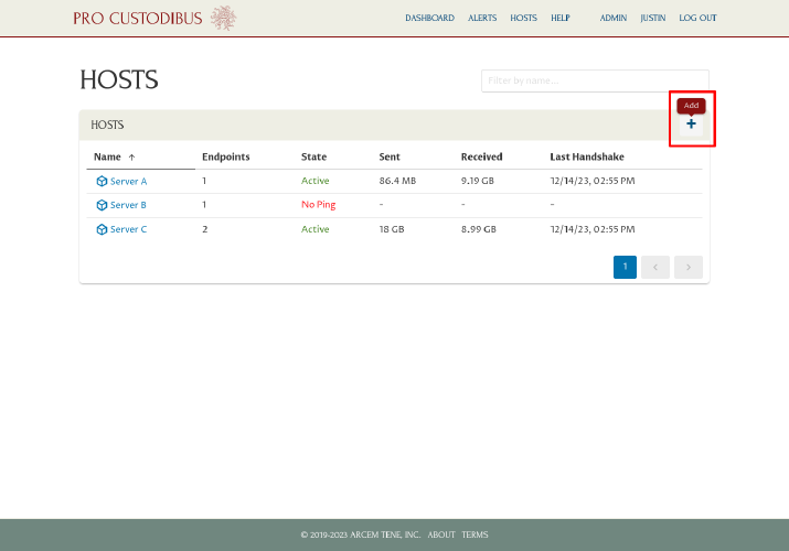
Next, log into https://pro.custodib.us/, navigate to the Hosts page, and click the Add icon:
Enter a display name for the host, like “VPN Server”, into the Name field. For the Configuration options, select the “Create new WireGuard configuration to push to host” radio button. Then click the Add button:
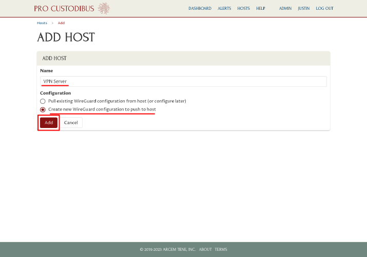
This will create a new host record for the server on Pro Custodibus, and launch you into the Connection Wizard.
Set up connection between server and first workstation
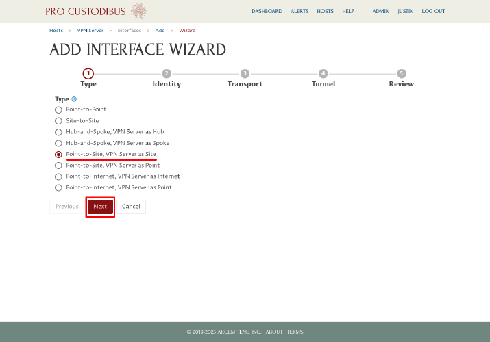
On the first step of the Connection Wizard, select the “Point-to-Site, as Site” radio button from the Type option list (many of the options will be customized with the host name you chose on the previous page, eg “Point-to-Site, VPN Server as Site”). Then click the Next button:
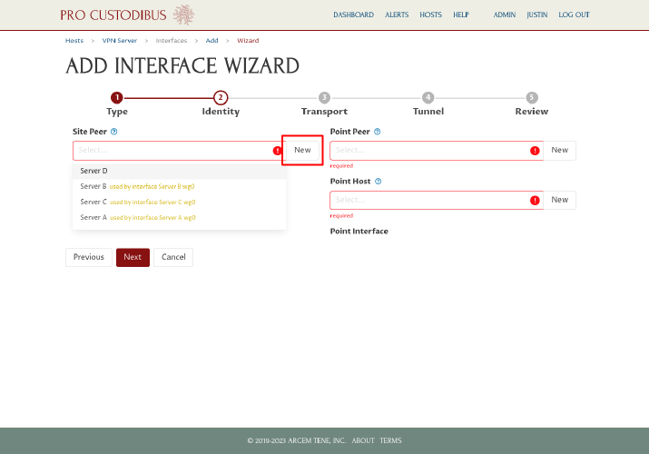
On the second step, click the New button next to the Site Peer field on the left side of the page:
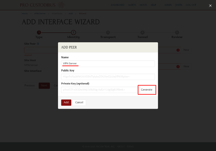
In the Add Peer dialog, enter a name for the WireGuard peer identity of the server, like “VPN Server”, into the Name field. Then click the Generate button to generate a new WireGuard key pair:
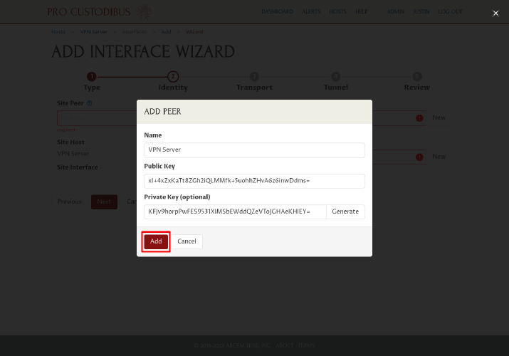
Click the Add button to add the new peer identity:
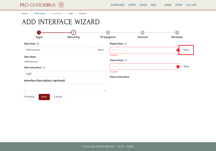
Then click the New button next to the Point Peer field on the right side of the page:
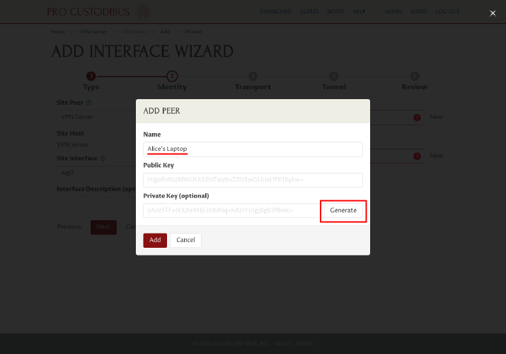
In the Add Peer dialog, enter a name for the peer identity of first workstation, like “Alice’s Laptop”, into the Name field. Then click the Generate button to generate a new key pair for it:
Click the Add button to add the new peer identity:
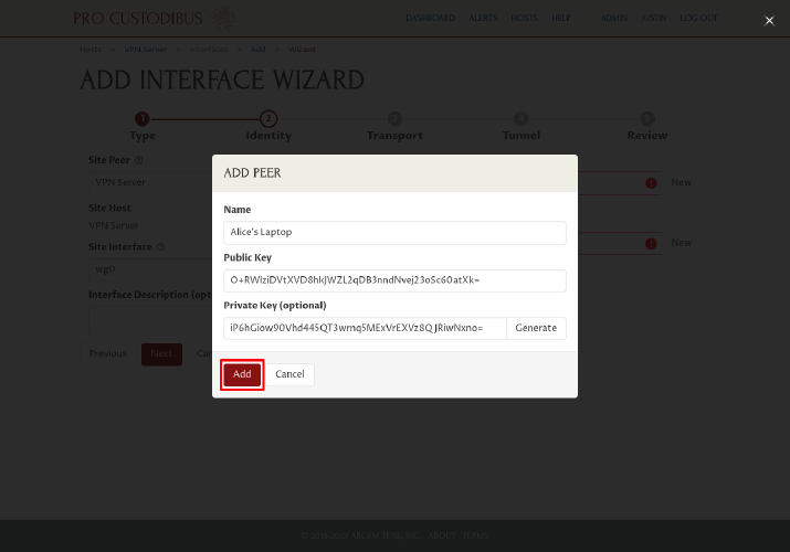
Next, click the New button next to the Point Host field on the right side of the page:
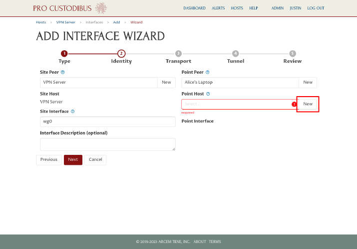
In the Add Host dialog, enter a display name for the first workstation, like “Alice’s Laptop”, into the Name field. Then click the Add button:
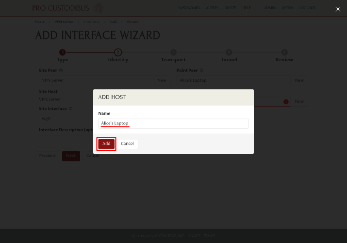
The wizard will auto-generate an interface name of wg0 for both site and point (in the Site Interface and Point Interface fields). The interface name is the host’s identifier for the interface; if you want a fuller description of an interface for your own memory (eg “cloud site network”), enter it into the optional Interface Description field. Click the Next button to continue:
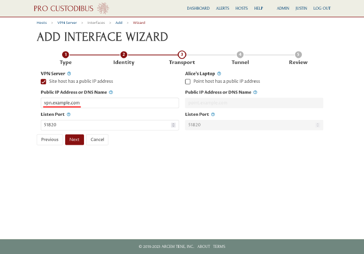
Based on the typical point-to-site arrangement, on the transport step the wizard will automatically check the “Site host has a public IP address” checkbox, and uncheck the “Point host has as public IP address” checkbox. This matches the arrangement in our scenario, too; so leave the checkboxes as is, and enter the public IP address (203.0.113.2) or DNS name (vpn.example.com) of the VPN server in the Public IP Address or DNS Name field on the left side of the page:
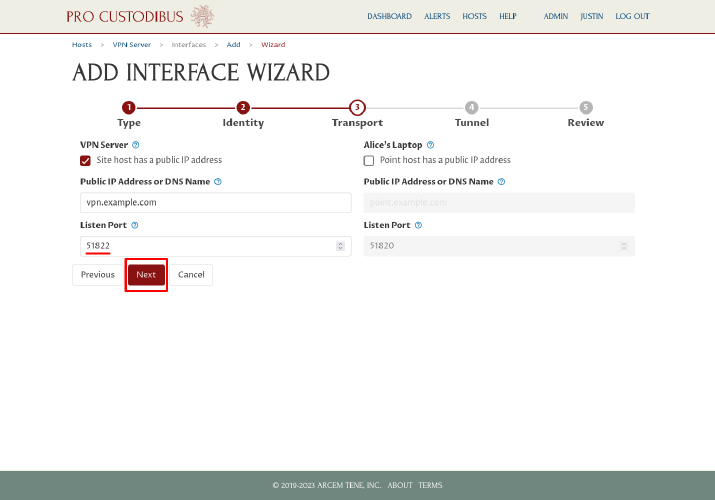
The wizard will also auto-generate a listen port of 51820 for the VPN server. We’ve already arranged to open up UDP port 51822 through the firewall for our example, however, so change the port to 51822, and then click the Next button:
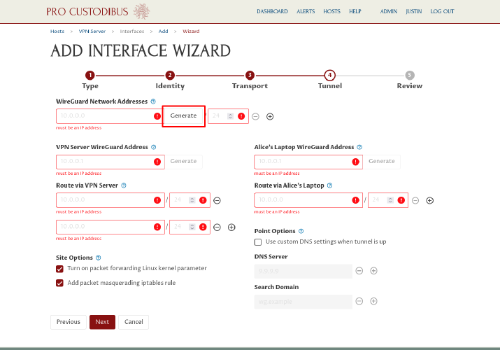
On the previous step, we had to enter the external public IP and port information for the connection transport. On the tunnel step, we enter the internal WireGuard IP addresses and routing we will use within the WireGuard tunnel. The first part of this is deciding on some internal network address space to use for our WireGuard network. If you already have a network address in mind (eg 10.0.0.0/24), enter it into the WireGuard Network Addresses field; otherwise, click the Generate button next to it:
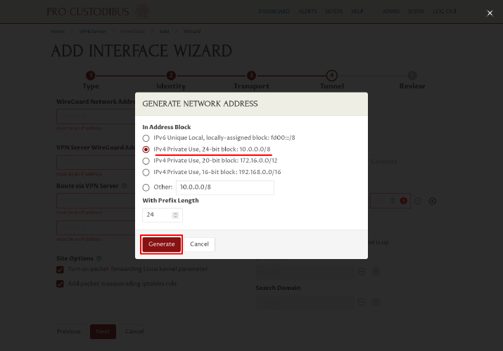
If you clicked the Generate button, in the Generate Network Address dialog, select a one of the primary private-use address blocks to use (like the “10.0.0.0/8” block), and then click the Generate button:
Adjust the generated network address (or generate a new one) as you like. If you want to enable the WireGuard connection to use both IPv4 and IPv6, click the Add icon next to the WireGuard Network Addresses field:
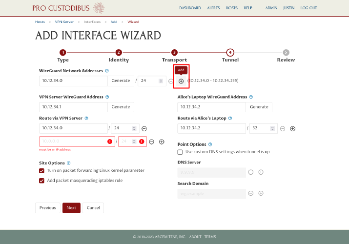
Then enter or generate a second address (an IPv4 address if the first address was IPv6, or IPv6 if the first was IPv4):
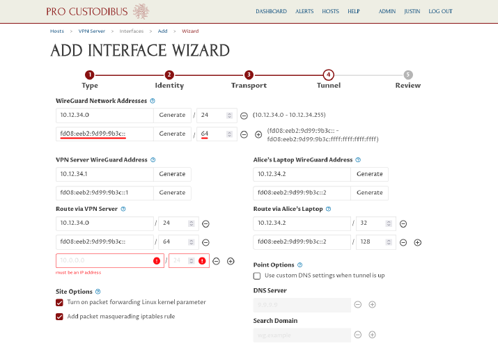
Notice that the wizard will automatically generate an individual WireGuard address on both sides of the connection (in this case labeled VPN Server WireGuard Address and Alice’s Laptop WireGuard Address) for each network address we selected in the WireGuard Network Addresses fields; and it will also add a route for each network address to both sides of the connection (labeled Route via VPN Server and Route via Alice’s Laptop):
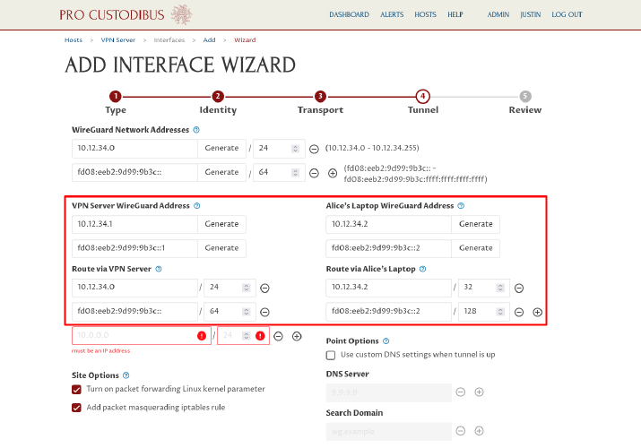
Click the Generate button next to each WireGuard address if you want to generate a random address within the network address space (or directly enter a different address of your choosing). If you change an address, the wizard may re-generate its suggested routes to match the change.
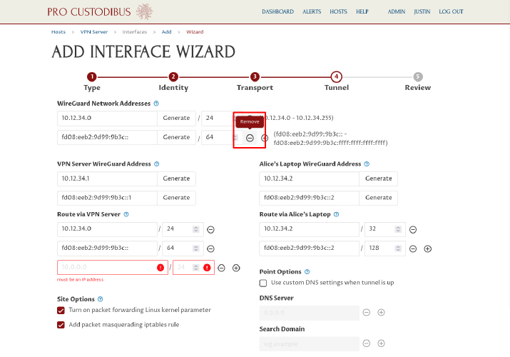
For our scenario, we’re going to use just IPv4, so we’ll remove the IPv6 network address we added, by clicking the Remove icon next to it:
In most cases, you’ll want to keep the routes auto-generated by the wizard (but you may adjust, remove, or add to them if you want something different). In a point-to-site scenario like this one, you’ll always want to add at least one route on the site side, for the LAN in use at the site — which is why the wizard has automatically added a blank route on the left side for us. We’ll fill in this field with our example site LAN network, 192.168.200.0/24:
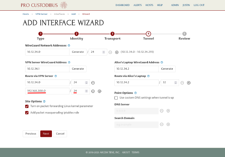
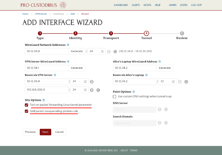
When setting up the site side of a point-to-site connection, the wizard will automatically select the “Turn on packet forwarding Linux kernel parameter” and “Add packet masquerading iptables rule” checkboxes for you. If the VPN server is running Linux (and won’t be running WireGuard in a container), and you haven’t explicitly turned on its net.ipv4.conf.all.forwarding (or net.ipv4.ip_forward) kernel parameters, leave the first checkbox checked; otherwise, uncheck it. Similarly, if the VPN server is running Linux, and you haven’t explicitly configured its firewall settings, leave the second checkbox checked; otherwise, uncheck it.
In our example, the VPN server is running Linux, and we haven’t configured any of its kernel parameters or firewall settings, so we’ll leave those two checkboxes checked:
|
Tip
|
If your VPN server will run WireGuard in a Docker container, or if it does not run Linux, do not check the “Turn on packet forwarding Linux kernel parameter” checkbox — you will need to enable packet forwarding outside of the wizard:
|
|
Tip
|
If you have (or want to) set up a firewall on a point-to-site VPN server running Linux, consult one of the following guides for details about the firewall rules you need to apply: If the VPN server is not running Linux, you’ll need to either configure the server’s firewall to SNAT connections from WireGuard to the site, or adjust the routing at the site to automatically route the WireGuard network ( |
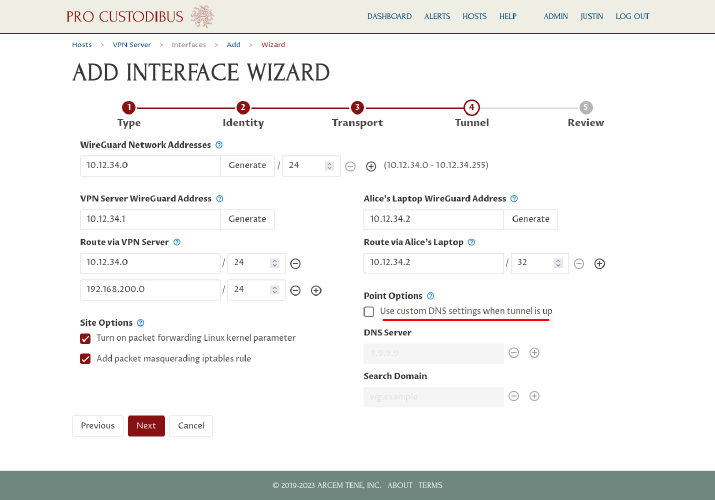
When setting up the point side of a point-to-site connection, the wizard will give you the option to configure custom DNS settings to apply to the point when the WireGuard tunnel is up. We don’t have a private DNS server at our example site, so we’ll leave the “Use custom DNS settings when tunnel is up” checkbox unchecked:
|
Tip
|
If you do want to set up a private DNS server at your site, see the Internal DNS Names With WireGuard article for a guide to setting up a simple CoreDNS server. If you did that, you would check the “Use custom DNS settings when tunnel is up” checkbox and enter the IP address of the DNS server into the DNS Server field above. |
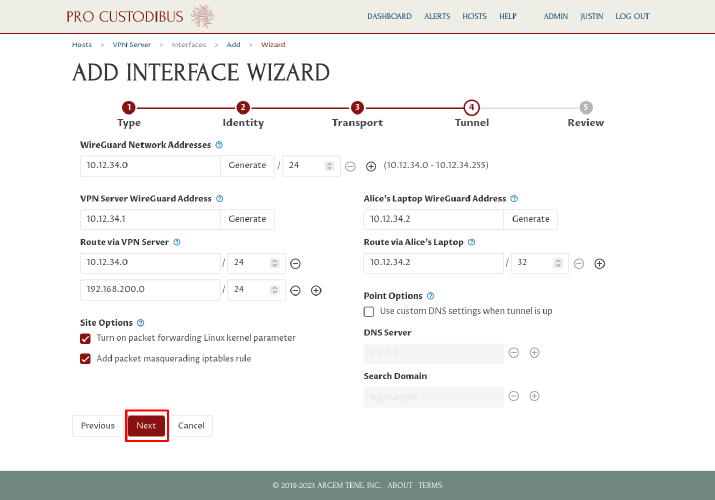
Click the Next button to continue on to the review step:
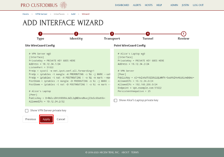
On the final step, you can review the WireGuard config settings that the wizard will generate, and go back and fix anything you want to do differently (or click the Cancel button to avoid setting up the connection entirely). On the left side of the page, the wizard will display the configuration it will generate for the VPN server; and on the right side of the page, the wizard will display the configuration it will generate for Alice’s laptop. Click the Apply button to save and apply it:
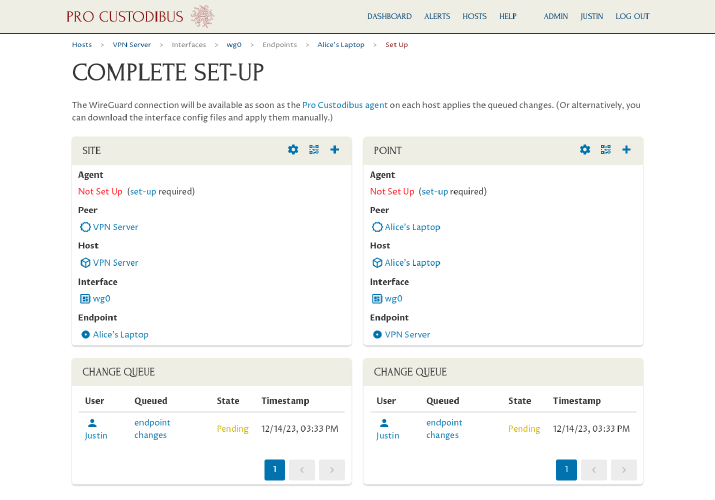
The wizard will send to you to the Complete Set-Up page, where the status of each side of the connection will be displayed:
Set up Pro Custodibus agent on server
In order to apply the pending WireGuard changes to the VPN server, we have two options:
-
Set up the Pro Custodibus agent on the VPN server; the Pro Custodibus agent will automatically apply the change for us.
-
Alternatively, download the WireGuard config file from Pro Custodibus, and apply it manually to the VPN server.
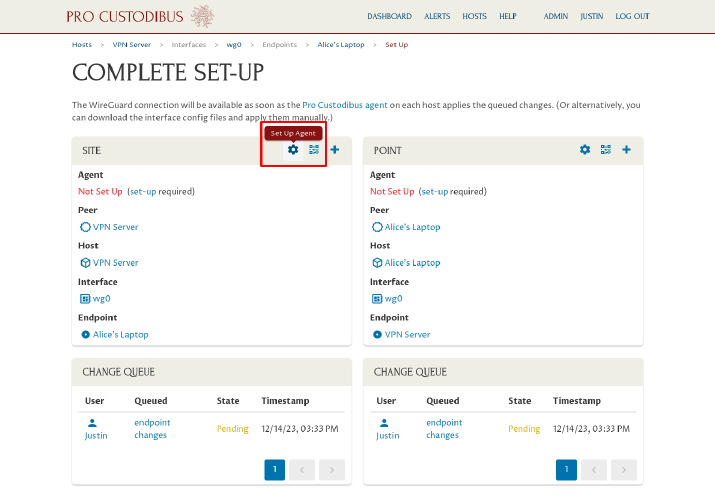
We’ll choose option 1: Set up the agent on the server. Click the Set Up Agent icon in the Site panel on the left side of the page:
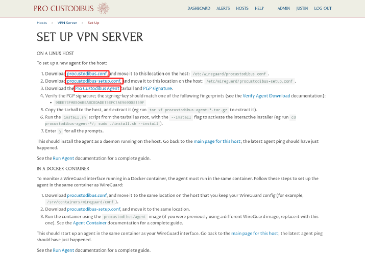
Download the procustodibus.conf and procustodibus-setup.conf files, as well as the Pro Custodibus Agent tarball:
Copy the procustodibus.conf and procustodibus-setup.conf files, along with the procustodibus-agent-latest.tar.gz tarball, to the VPN server. On the VPN server, move the procustodibus.conf and procustodibus-setup.conf files to the /etc/wireguard/ directory:
$ sudo mv procustodibus.conf /etc/wireguard/.
$ sudo mv procustodibus-setup.conf /etc/wireguard/.
Then extract the procustodibus-agent-latest.tar.gz tarball, change to the procustodibus-agent-*/ directory it creates, and run the install.sh script:
$ tar xf procustodibus-agent-latest.tar.gz
$ cd procustodibus-agent-*/
$ sudo ./install.sh --install --force
running as root
force install 1.4.3
agent configuration found at /etc/wireguard/procustodibus.conf
agent setup found at /etc/wireguard/procustodibus-setup.conf
...
WARNING daemon dead
OK will start daemon
Created symlink /etc/systemd/system/default.target.wants/procustodibus-agent.service → /etc/systemd/system/procustodibus-agent.service.
started daemon
install SUCCESS
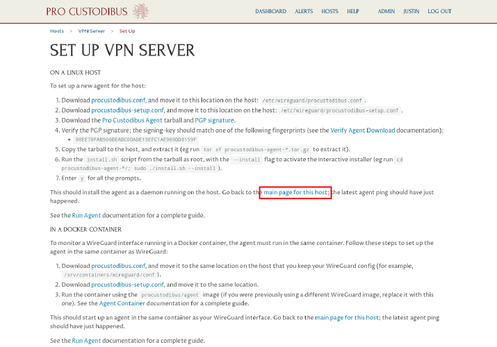
Return to the Pro Custodibus UI, and navigate to the main page for the VPN server:
You should see that the agent has connected to the Pro Custodibus servers successfully, that its new WireGuard interface is up but inactive, and that its endpoint to Alice’s laptop is available:
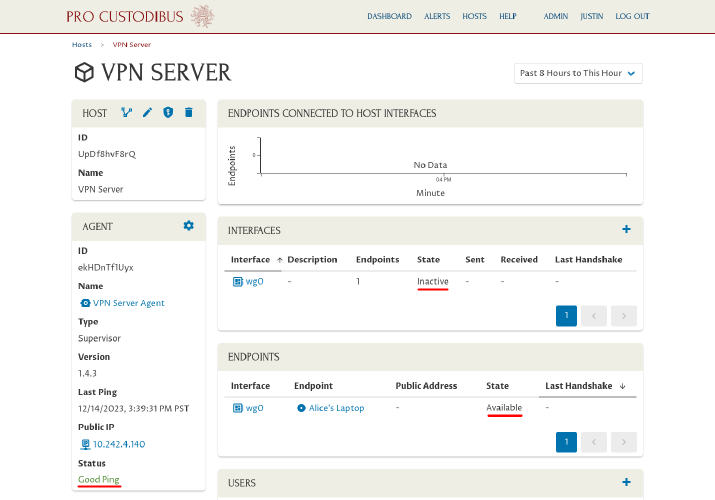
However, Alice cannot use the connection yet, since the WireGuard configuration on her side of the connection has not yet been applied.
Set up Pro Custodibus agent on first workstation
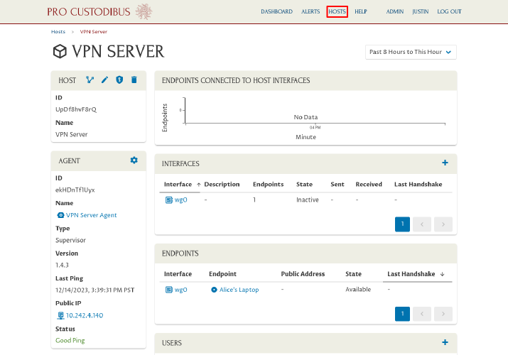
To apply the pending WireGuard changes to the Alice’s laptop, we’ll set up the Pro Custodibus agent on it. Click the Hosts link at the top of the page:
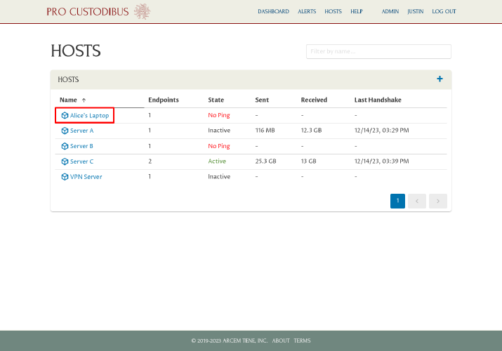
Then click the link to Alice’s Laptop in the Hosts panel:
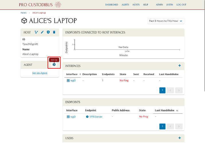
On the main page for Alice’s laptop, click the Set Up icon in the Agent panel:
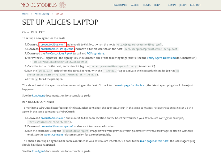
From the Set Up Alice’s Laptop page, click the procustodibus.conf and procustodibus-setup.conf files (as well as the Pro Custodibus Agent tarball if you already deleted the copy used to set up the VPN server above):
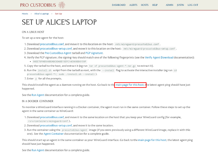
Copy the procustodibus.conf and procustodibus-setup.conf files, along with the procustodibus-agent-latest.tar.gz tarball, to Alice’s laptop. On Alice’s laptop, move the procustodibus.conf and procustodibus-setup.conf files to the /etc/wireguard/ directory:
$ sudo mv procustodibus.conf /etc/wireguard/.
$ sudo mv procustodibus-setup.conf /etc/wireguard/.
|
Note
|
On platforms where WireGuard config files are stored in a different config directory, such as |
Then extract the procustodibus-agent-latest.tar.gz tarball, change to the procustodibus-agent-*/ directory it creates, and run the install.sh script:
$ tar xf procustodibus-agent-latest.tar.gz
$ cd procustodibus-agent-*/
$ sudo ./install.sh --install --force
running as root
force install 1.4.3
agent configuration found at /etc/wireguard/procustodibus.conf
agent setup found at /etc/wireguard/procustodibus-setup.conf
...
WARNING daemon dead
OK will start daemon
Created symlink /etc/systemd/system/default.target.wants/procustodibus-agent.service → /etc/systemd/system/procustodibus-agent.service.
started daemon
install SUCCESS
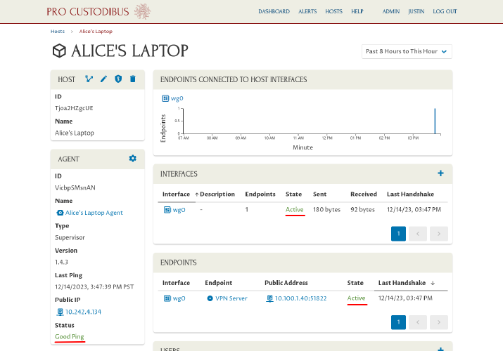
Return to the Pro Custodibus UI, and navigate to the main page for Alice’s laptop:
You should see that the agent has connected to the Pro Custodibus servers successfully, and that its new WireGuard interface is up and active (sending keepalive packets to the VPN server):
Now Alice can access any of the other computers in the VPN server’s LAN (in the 192.168.200.0/24 network). For example, if there was a web server running at 192.168.200.22, Alice can run the following cURL command on her laptop to access it:
$ curl 192.168.200.22
<!DOCTYPE HTML PUBLIC "-//W3C//DTD HTML 4.01//EN" "http://www.w3.org/TR/html4/strict.dtd">
<html>
...
Set up connection between server and second workstation
Now that we have a working connection between the VPN server and Alice’s laptop, it will be easy to duplicate it for additional connections. To do so, in the Pro Custodibus web UI, click the Hosts link at the top of the page:
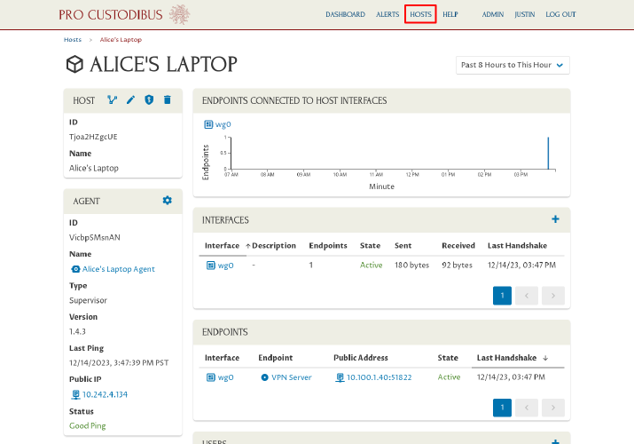
Click the VPN Server link in the Hosts panel:
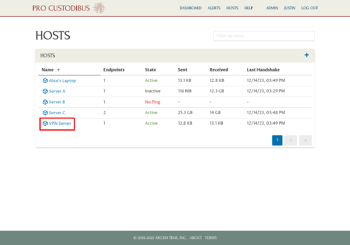
And click the wg0 link in the Interfaces panel:
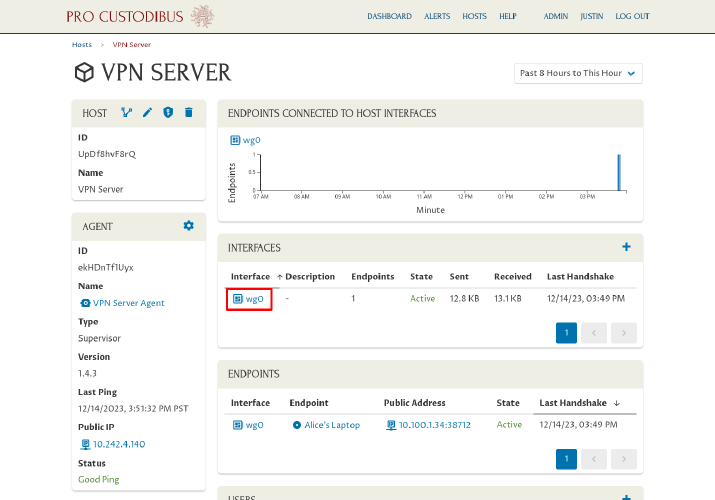
Now click the Add icon in the Endpoints panel to add a new endpoint for Bob’s workstation:
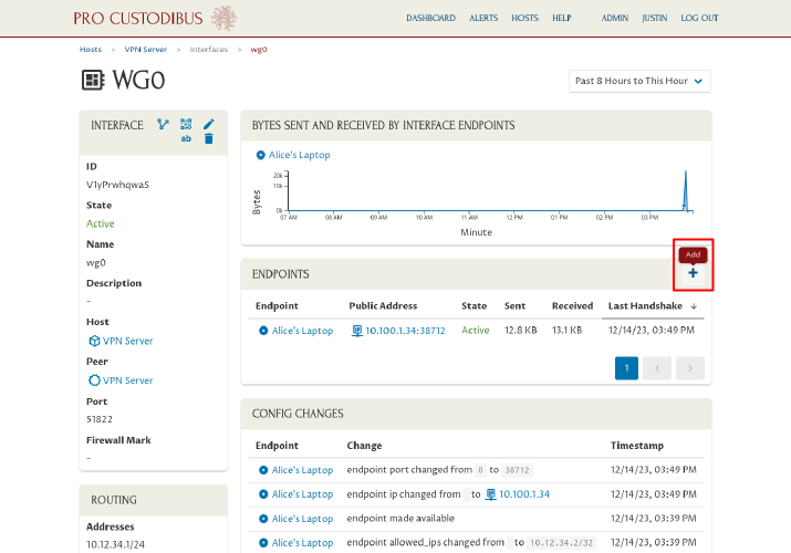
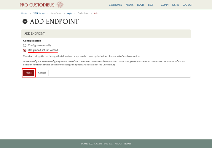
For Configuration, select the “Use guided set-up wizard” radio button, and then click the Next button to launch the Connection Wizard:
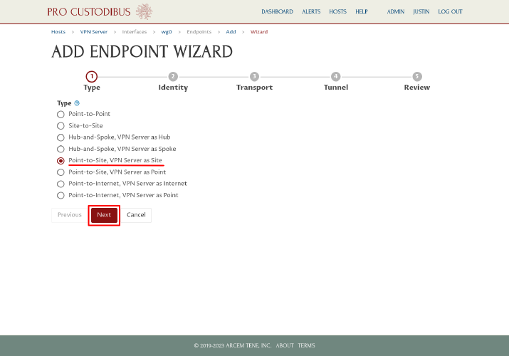
On the first step of the Connection Wizard, select the “Point-to-Site, as Site” radio button from the Type option list (many of the options will be customized with the VPN server’s name, eg “Point-to-Site, VPN Server as Site”). Then click the Next button:
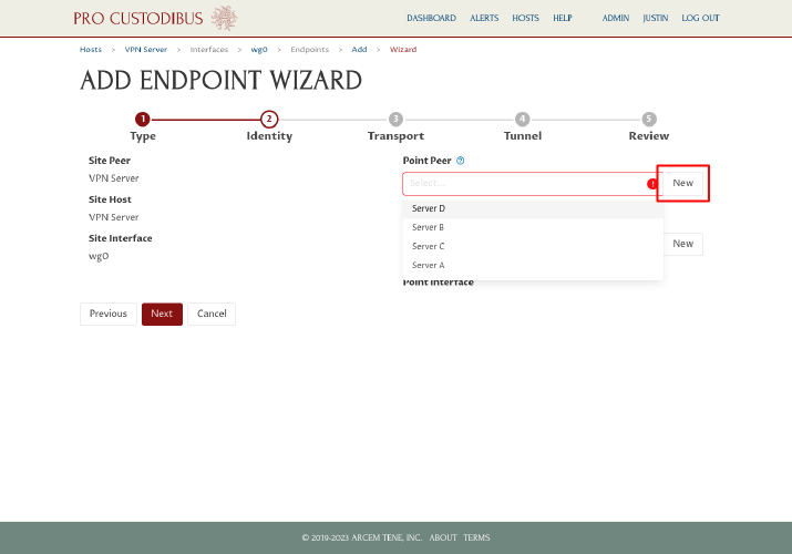
On the second step, click the New button next to the Point Peer field on the right side of the page:
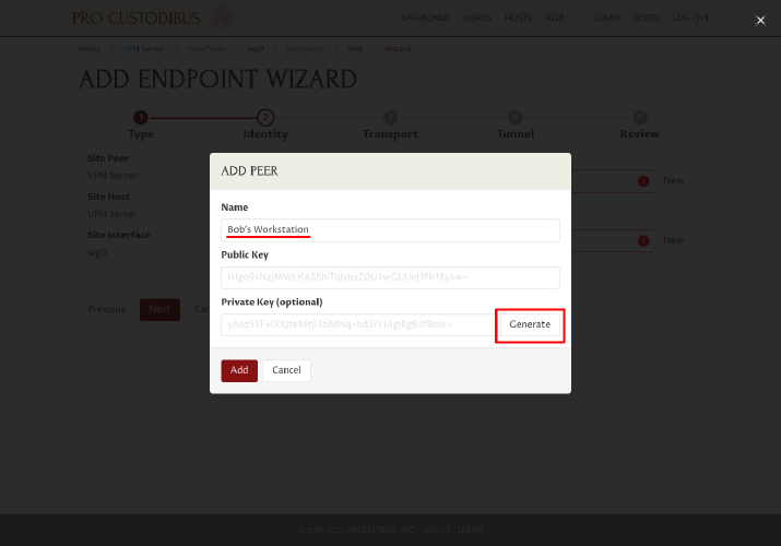
In the Add Peer dialog, enter a name for the WireGuard peer identity of second workstation, like “Bob’s Workstation”, into the Name field. Then click the Generate button to generate a new WireGuard key pair:
Click the Add button to add the new peer identity:
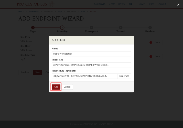
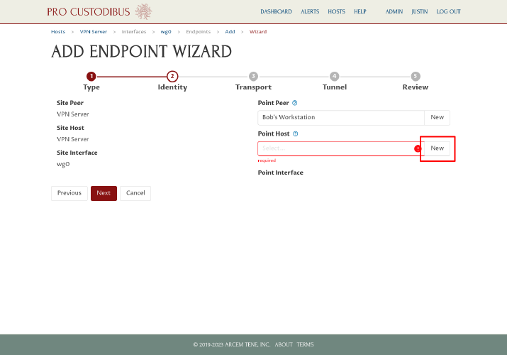
Next, click the New button next to the Point Host field on the right side of the page:
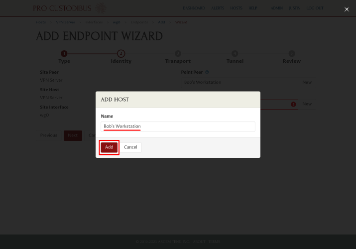
In the Add Host dialog, enter a display name for the second workstation, like “Bob’s Workstation”, into the Name field. Then click the Add button:
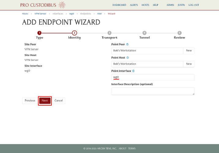
The wizard will auto-generate an interface name of wg0 for the new point. Click the Next button to continue:
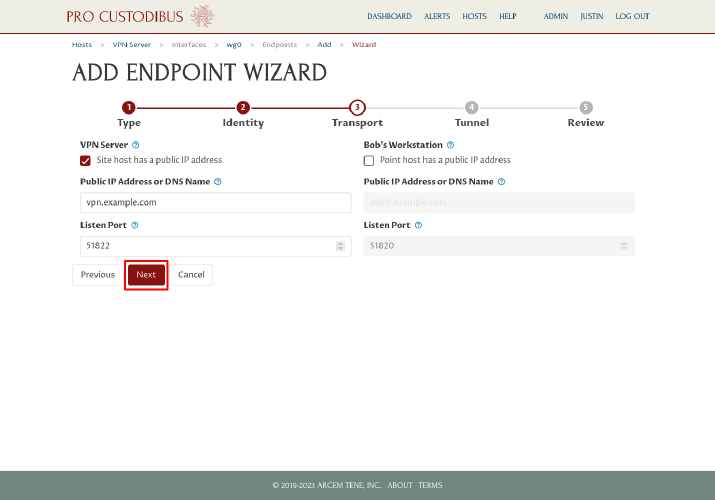
On the next step the wizard will automatically check the “Site host has a public IP address” checkbox, and uncheck the “Point host has as public IP address” checkbox; leave the checkboxes as is. The wizard will also automatically fill in the Public IP Address or DNS Name field on the left side of the page, using the DNS name (vpn.example.com) of the VPN server that we used when we set up the first workstation. It will also do the same for the Listen Port field (51822). Click the Next button to use these settings for the second workstation:
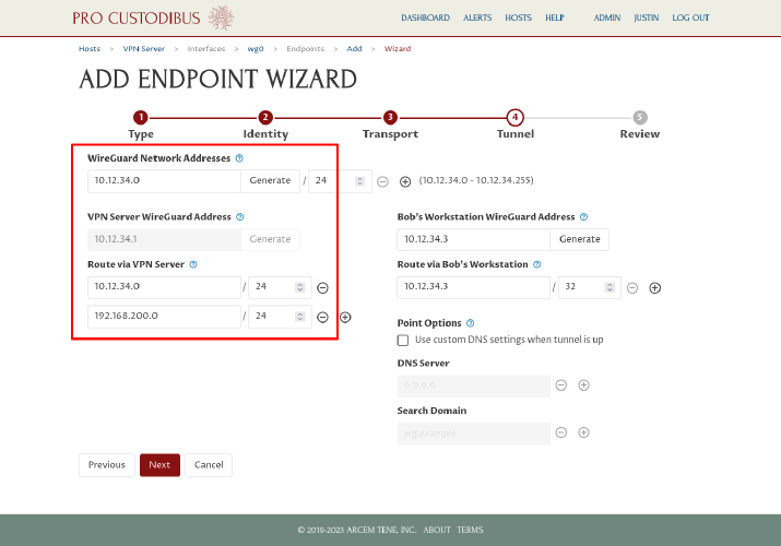
On the tunnel step the wizard will also automatically fill in all the fields we need, based on the settings we used when we set up the first endpoint. The wizard fill in the same WireGuard Network Adresses, VPN Server WireGuard Address, and Route via VPN Server values used with the first endpoint on the left side of the page:
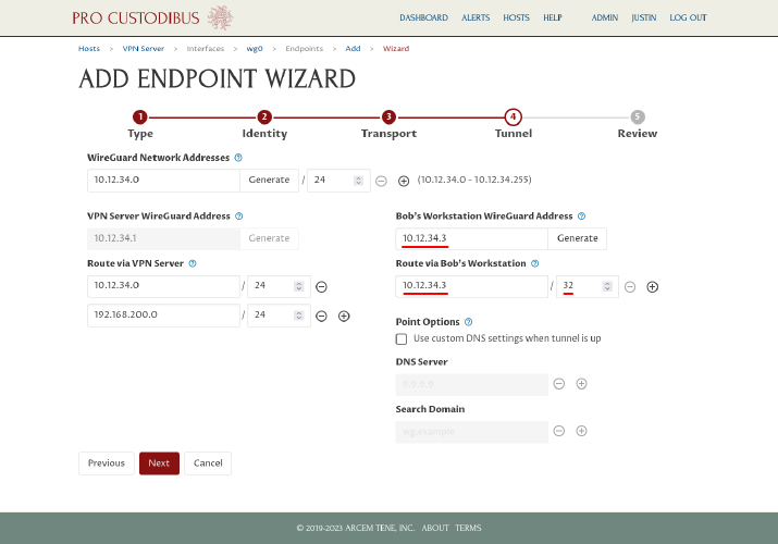
On the right side of the page, for the Bob’s Workstation WireGuard Address field, the wizard will automatically fill in the lowest available IP address in the WireGuard network address space (10.12.34.3). It will use that same address for the Route via Bob’s Workstation field:
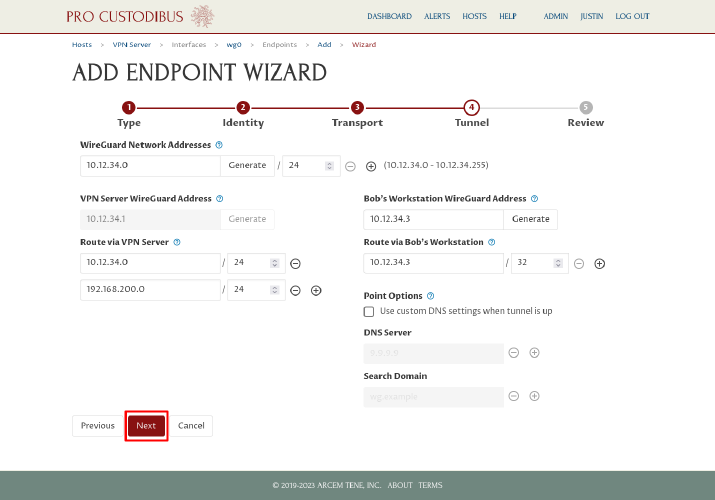
Enter a different address if you like (or click the Generate button next to the Bob’s Workstation WireGuard Address field to generate a random address within the WireGuard network address space), then click the Next button:
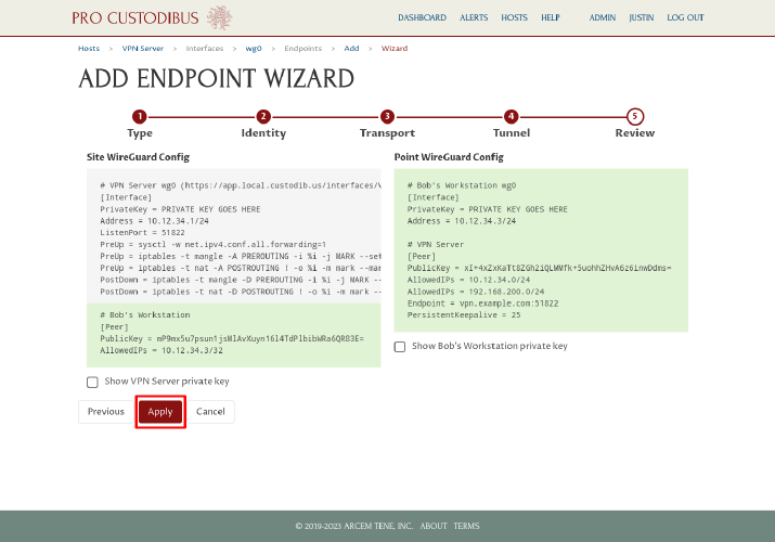
On the final step, review the WireGuard config changes that will be made. Notice that on the left side, only the bottom part of the config is highlighted with a green background — this is part that will be added (the top gray part shows the unchanged core interface settings). Click the Apply button to save and apply the changes:
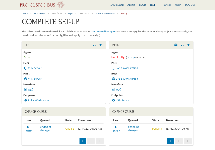
The wizard will send to you to the Complete Set-Up page, where the status of each side of the connection will be displayed:
Download WireGuard config and apply to second workstation
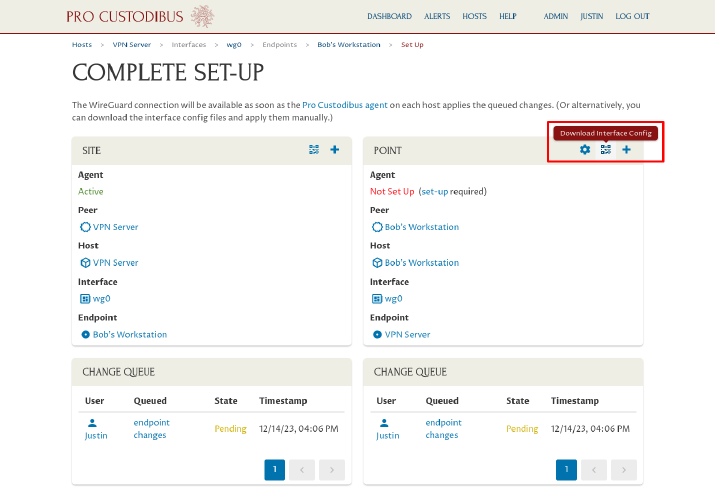
Since we have already installed the Pro Custodibus agent on the VPN server, the config changes to the VPN server will automatically be applied by the agent momentarily. But we have not (and will not) installed the agent on Bob’s workstation. Instead, click the Download Interface Config icon in the Point panel on the right side of the page:
Then click the Download button on the wg0 interface configuration page:
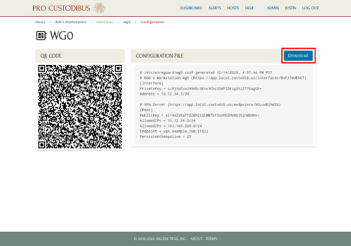
Install WireGuard on Bob’s workstation, copy the wg0.conf file you just downloaded over to it, and move the file into the /etc/wireguard directory (or use the WireGuard app on Windows or macOS to import the wg0.conf file).
Start up the new WireGuard interface on Bob’s workstation, and now Bob can access any of the other computers in the VPN server’s LAN (in the 192.168.200.0/24 network). For example, if there was a web server running at 192.168.200.22, Bob can access it by entering http://192.168.200.22 into the address bar of his web browser.
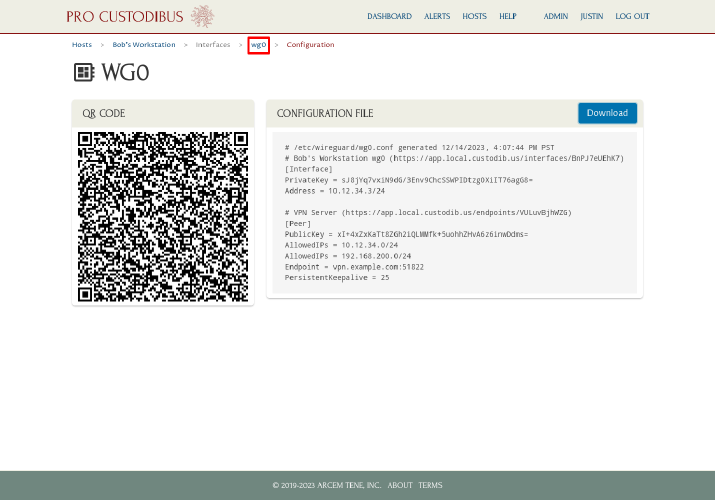
Finally, go back to Pro Custodibus, and navigate to the main wg0 interface page for Bob’s laptop:
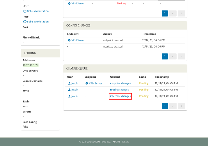
Scroll down, and click on the last link in the Queued column of the Change Queue panel:
Click the Applied Manually icon in the Queued Change panel:
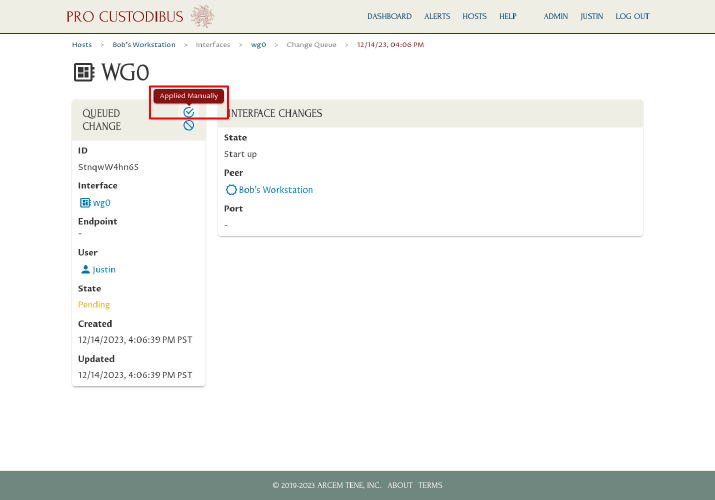
This will notify Pro Custodibus that you applied this change manually, so it will stop listing the change as pending:
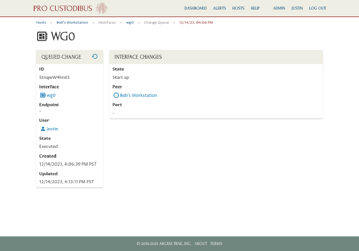
Go back and do the same for the other pending changes, so that each change is listed as Executed:
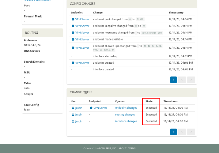
Doing this will ensure that if you use the Connection Wizard in the future to add another connection to Bob’s laptop, Pro Custodibus will know what settings have been applied to Bob’s laptop, so the wizard will be able to make appropriate suggestions for the new connection.
Existing Point-to-Point WireGuard Network
For our second scenario, we’ll add to a new connection between two servers in an existing point-to-point WireGuard network. We’ve previously used Pro Custodibus to set up a WireGuard interface on both of these two servers (to connect to other servers), so using Pro Custodibus to add another connection on each will require just a few more clicks.
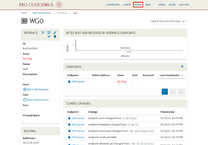
Start by navigating to the Hosts page in the Pro Custodibus web UI:
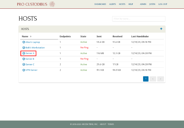
Click the link to the first server (Server A in this example) in the Hosts panel:
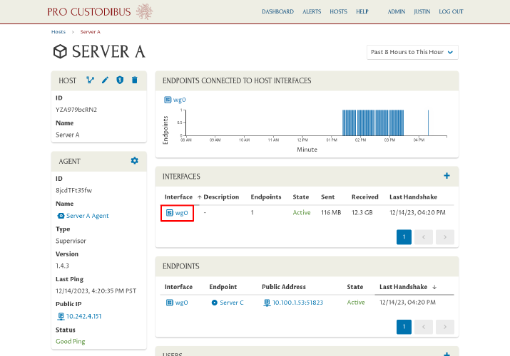
Click the link to the existing interface (wg0 in this example) in the Interfaces panel to which we want to add the new connection:
Then click the Add icon in the Endpoints panel:
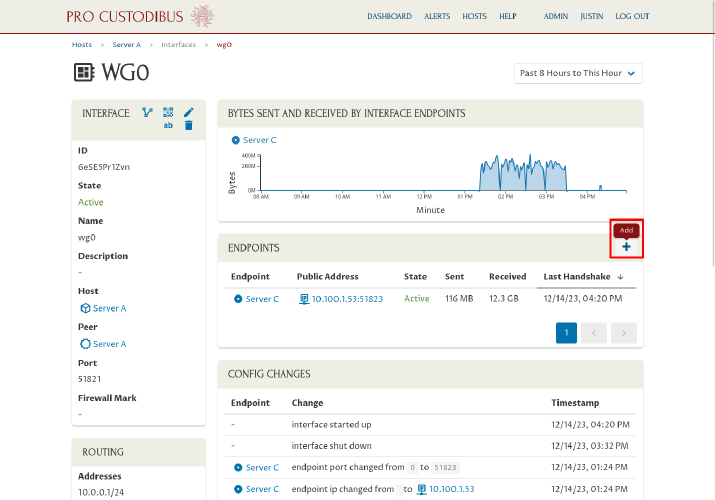
For Configuration, select the “Use guided set-up wizard” radio button, and then click the Next button to launch the Connection Wizard:
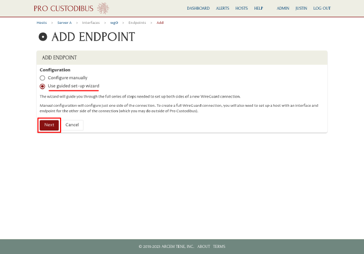
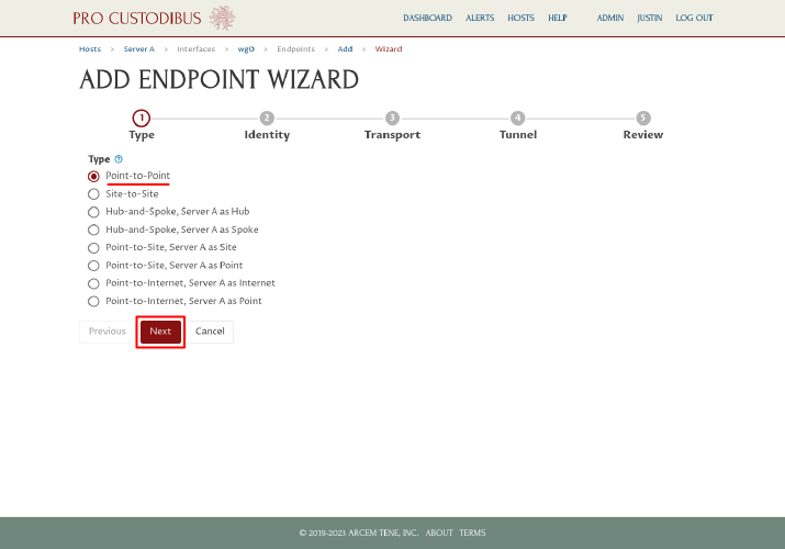
As we just want a simple point-to-point connection, on the first step of the Connection Wizard, select the “Point-to-Point” radio button from the Type option list. Then click the Next button:
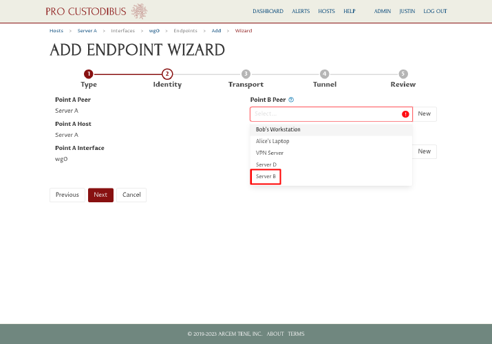
On the second step, select the existing WireGuard peer identity of the second server (Server B in this example) in the Point B Peer field on the right side of the page:
|
Tip
|
If you don’t see the peer you want to select in the dropdown list, start typing its name in the Point B Peer field to filter the list. |
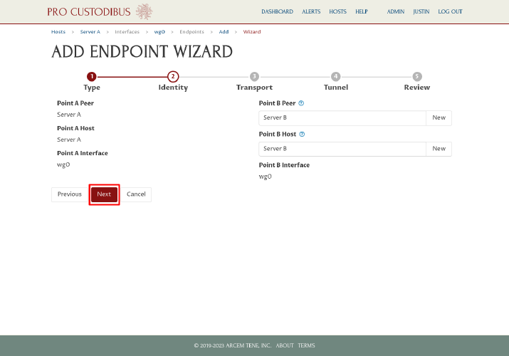
Since we have previously set up a WireGuard interface for Server B through Pro Custodibus, the wizard will automatically find and select the registered host and WireGuard interface that matches the peer we selected. Click the Next button to continue to the next step:
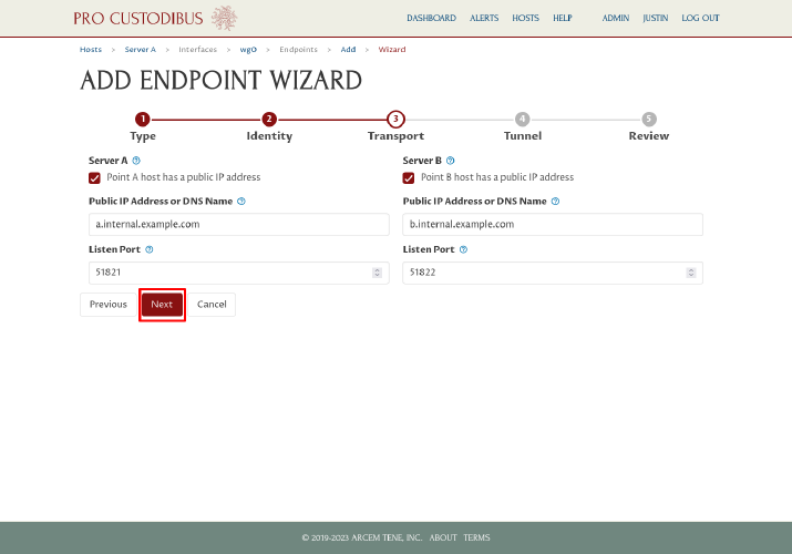
On the third step, because we had previously configured the public IP address and listen port for each server, we can simply click the Next button:
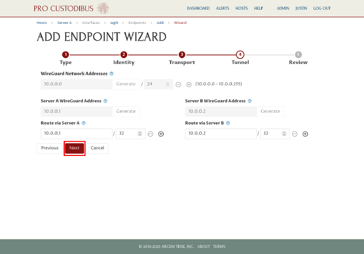
On the fourth step, the wizard will display the WireGuard network address space and addresses we are currently using for the selected interfaces, and automatically fill in the appropriate routes for a point-to-point connection between the two interfaces. Again, all we have to do is click the Next button:
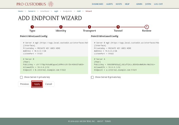
On the final step, we can review the WireGuard config changes that will be made. Notice that on both sides, only the bottom part of each config is highlighted with a green background — the highlighted part shows what will be added (the top gray parts on both sides show the unchanged core interface settings). Click the Apply button to save and apply the changes:
The wizard will send to you to the Complete Set-Up page, where the status of each side of the connection will be displayed:
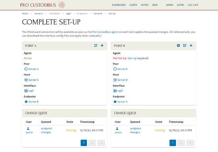
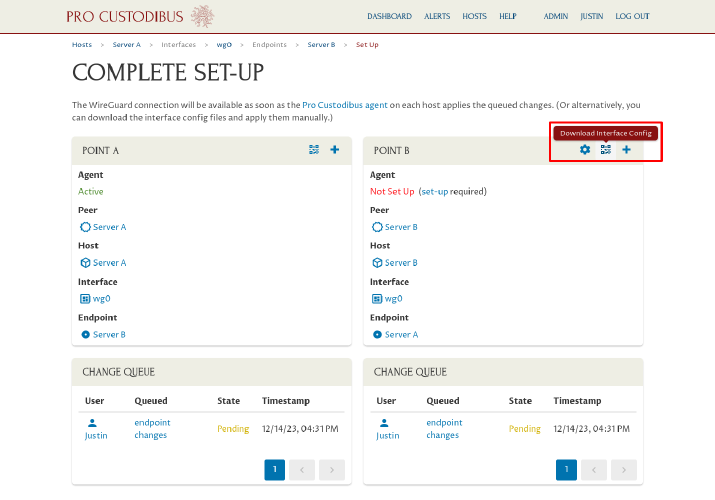
In this example, we have already installed the Pro Custodibus agent on Server A, so the config changes to Server A will automatically be applied by the agent (in a minute or two). But we have not (and will not) install the agent on Server B. Instead, we’ll apply the changes manually. Click the Download Interface Config icon in the Point B panel on the right side of the page:
Then click the Download button on the wg0 interface configuration page:
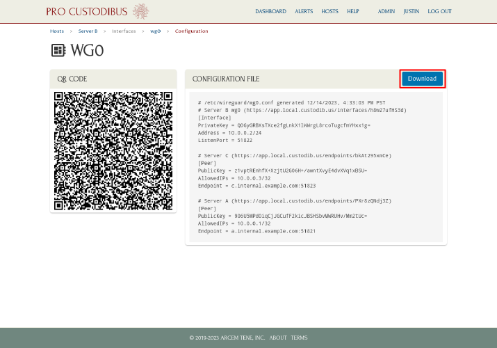
(Notice that this page shows the full config settings for Server B — including an endpoint to Server C that we had previously added — whereas the review step in the Connection Wizard only shows the core interface settings and the new endpoint to Server A.)
Copy the wg0.conf file you just downloaded over to Server B, replace Server B’s existing /etc/wireguard/wg0.conf file with it, and then run the following command to apply the updated configuration on Server B:
$ sudo bash -c 'wg syncconf wg0 <(wg-quick strip wg0)'
|
Tip
|
Alternatively, instead of running the above command, you could just shut down the WireGuard interface and then start it up again. |
You should now be able to use the point-to-point WireGuard tunnel to connect from Server B to Server A (or vice versa):
$ ping -nc1 10.0.0.1
PING 10.0.0.1 (10.0.0.1) 56(84) bytes of data.
64 bytes from 10.0.0.1: icmp_seq=1 ttl=64 time=1.53 ms

--- 10.0.0.1 ping statistics ---
1 packets transmitted, 1 received, 0% packet loss, time 0ms
rtt min/avg/max/mdev = 1.527/1.527/1.527/0.000 ms
Finally, go back to Pro Custodibus, and navigate to the main wg0 interface page for Server B:
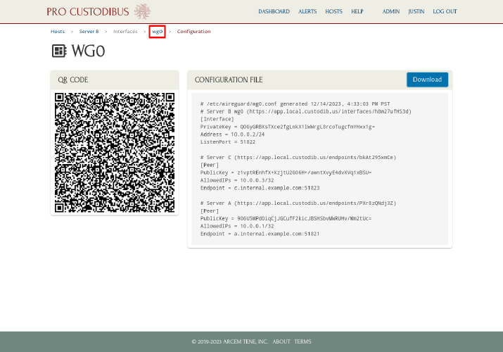
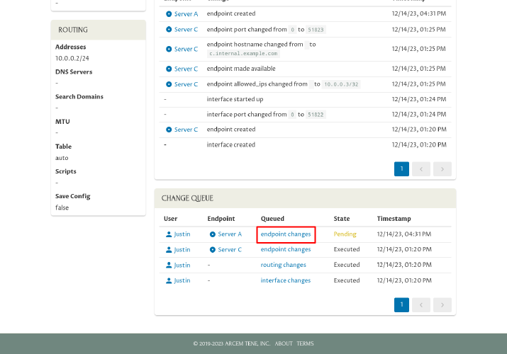
Scroll down, and click on the pending endpoint changes link in the Change Queue panel:
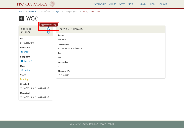
Click the Applied Manually icon in the Queued Change panel:
This will notify Pro Custodibus that you applied this change manually, so it will stop listing the change as pending:
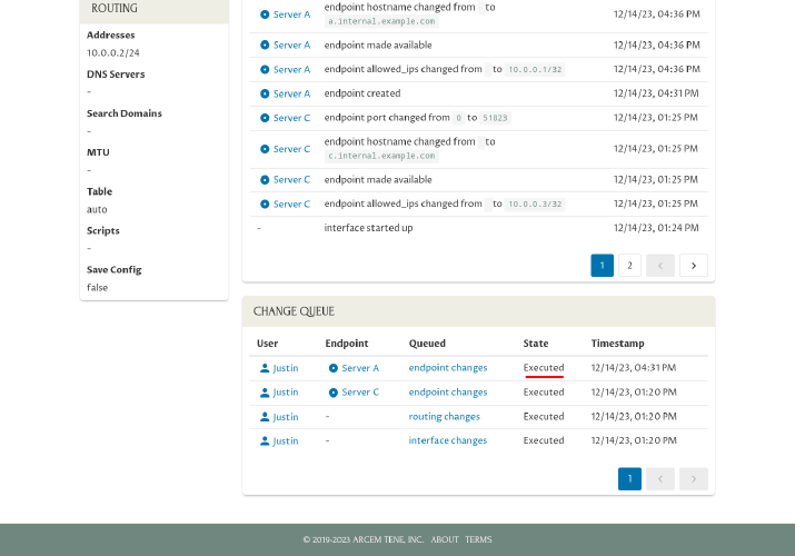
And more importantly, it will make sure that the next time you use the Connection Wizard with Server B, Pro Custodibus will know what settings have been applied to Server B, so it can make appropriate suggestions for new connections.