OPNsense Push Routes Through WireGuard Via OSPF
In the OPNsense WireGuard Site-to-Site article, we demonstrated how to set up a site-to-site connection between an OPNsense router and a Linux router via WireGuard. In this article, we’ll show you how to use OSPF (Open Shortest Path First, an Internal Gateway Protocol, or IGP) to exchange routes between the two routers over WireGuard.
Using OSPF like this allows you to make routing changes at one site without having to update the WireGuard configuration on the other site’s router. (For an example of using OSPF in a different use-case, to maintain redundant WireGuard connections between two sites, see the High Availability WireGuard Site to Site article.)
In this article, we’ll build upon the basic site-to-site WireGuard configuration we set up in the original OPNsense WireGuard Site-to-Site article, where we connected a vanilla Linux router (Router A) in Site A to an OPNsense router (Router B) in Site B:

First, we’ll make a few adjustments to the WireGuard configuration from the original article to allow the routers to use OSPF with WireGuard:
Then we’ll install the FRR routing suite on both routers, and configure each to exchange routes via OSPF through their WireGuard connection:
|
Note
|
In this article, we’ll show you how to use OSPFv2, which supports IPv4 routes only. If you want to exchange IPv6 routes, you should instead use OSPFv3. OSPFv3, however, requires the use of IPv6 link-local addresses on all interfaces participating in OSPF exchanges — so use OSPFv3 only if you’re already using IPv6 at both sites; otherwise, use OSPFv2. |
Adjust WireGuard Routes on Linux
In order for OSPF to work over a WireGuard connection, the WireGuard interfaces on both sides of the connection must be part of the same subnet. In the original OPNsense WireGuard Site-to-Site guide, we used a separate /32 subnet for each interface. To enable OSPF, we need to update the addresses for the WireGuard interfaces on Router A and on Router B to use the same 10.0.0.0/24 subnet.
Also, we need to allow each router to be able to access the other using the other’s WireGuard address — as well as the OSPF multicast addresses — so at minimum we would need to adjust the AllowedIPs setting for each to include the other’s WireGuard address (10.0.0.1 for Router A and 10.0.0.2 for Router B) and the OSPF multicast addresses (224.0.0.5 and 224.0.0.6). But since the point of this exercise is to use FRR to manage routes dynamically, instead of pre-configuring them statically, we’ll use 0.0.0.0/0 as the AllowedIPs setting on each router (to allow any IPv4 address), and set the Table setting to off on each (to turn off wg-quick‘s route management).
So edit the /etc/wireguard/wg0.conf file on Router A to use these settings:
# /etc/wireguard/wg0.conf

# local settings for Router A
[Interface]
PrivateKey = AAAAAAAAAAAAAAAAAAAAAAAAAAAAAAAAAAAAAAAAAEE=
Address = 10.0.0.1/24
ListenPort = 51821
Table = off

# remote settings for Router B
[Peer]
PublicKey = fE/wdxzl0klVp/IR8UcaoGUMjqaWi3jAd7KzHKFS6Ds=
Endpoint = 203.0.113.2:51822
AllowedIPs = 0.0.0.0/0
|
Caution
|
These changes will prevent Router A from routing packets to Site B until you get OSPF up and running — so do this only when you can afford some downtime between Site A and Site B. |
Adjust WireGuard Routes on OPNsense
Similarly, on Router B, we need to adjust its WireGuard interface to use the same 10.0.0.0/24 subnet as Router A; and we also need to prevent the WireGuard service from automatically adding routes.
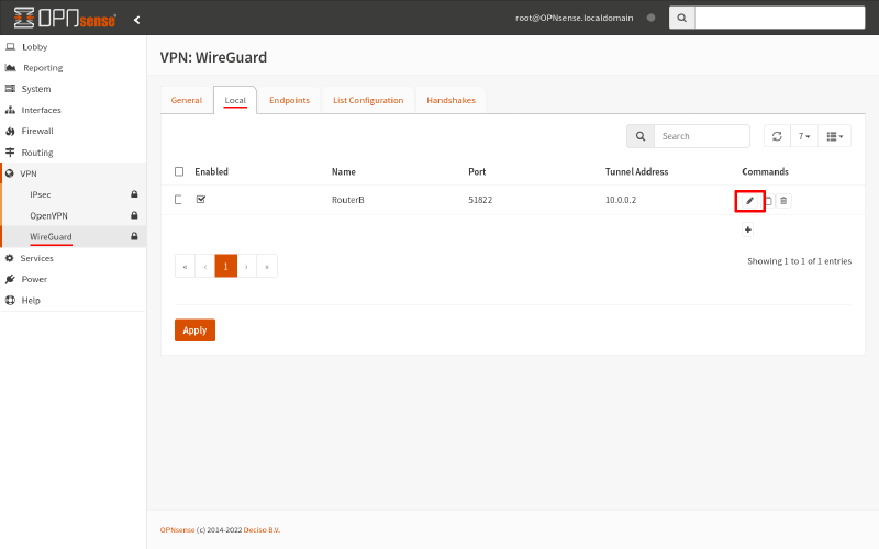
So navigate to the VPN > WireGuard page of the OPNsense GUI (Graphical User Interface), and switch to its Local tab. Click the Edit icon for the WireGuard interface:
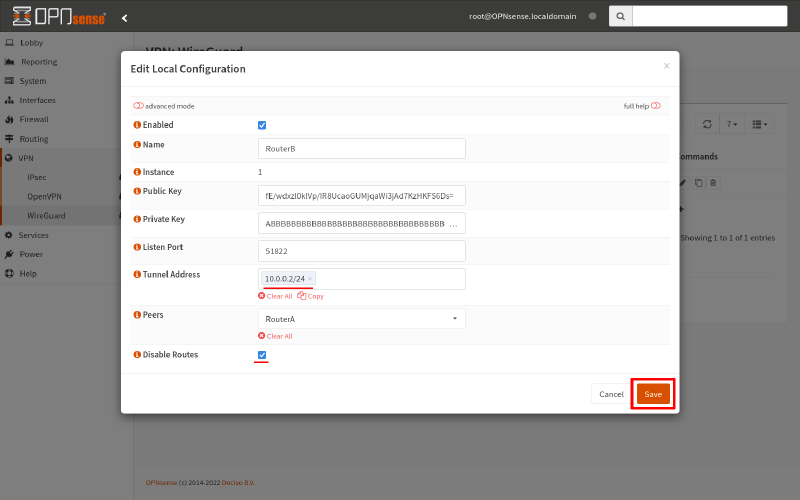
Change its Tunnel Address to 10.0.0.2/24, and check the Disable Routes checkbox. Then click Save:
Next, we need to allow access through the WireGuard tunnel to any packets that are routed to it.
So switch to the Endpoints tab. Click the Edit icon for the endpoint to Router A:
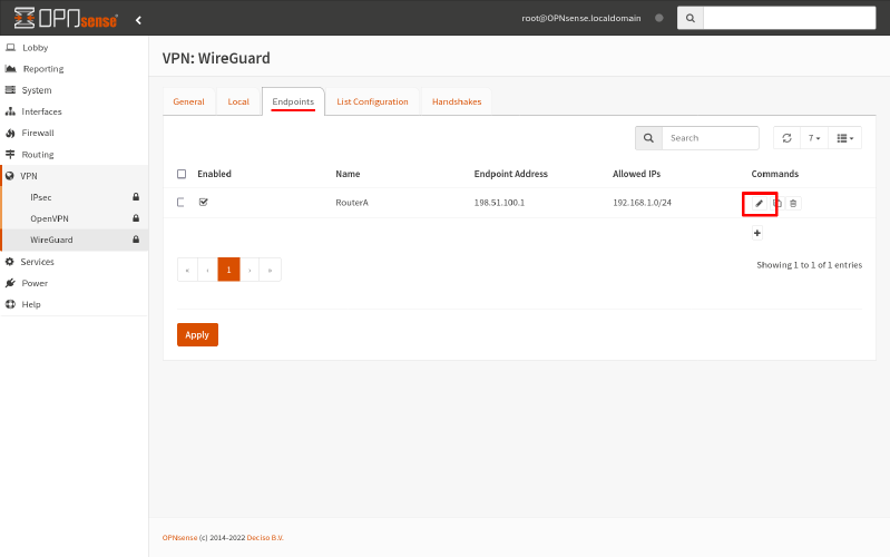
Change its Allowed IPs to 0.0.0.0/0. Then click click Save:
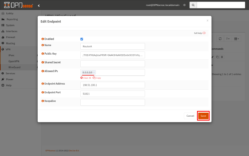
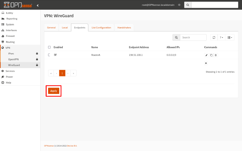
Finally, click the Apply button (on any WireGuard tab) to apply your changes:
|
Caution
|
These changes will prevent Router B from routing packets to Site A until you get OSPF up and running — so do this only when you can afford some downtime between Site A and Site B. |
Adjust WireGuard Firewall on Linux
Back on Router A, if you’re running a firewall on it, make sure it allows OSPF packets on its WireGuard interface.
To update the nftables ruleset from the original OPNsense WireGuard Site-to-Site guide to allow this, update the its input chain with a line that includes ip protocol ospf accept:
#!/usr/sbin/nft -f
flush ruleset

define wan_iface = "eth0"
define lan_iface = "eth1"
define wg_iface = "wg0"
define wg_port = 51821

table inet filter {
    chain input {
        type filter hook input priority 0; policy drop;

        # accept all loopback packets
        iif "lo" accept
        # accept all icmp/icmpv6 packets
        meta l4proto { icmp, ipv6-icmp } accept
        # accept all packets that are part of an already-established connection
        ct state vmap { invalid : drop, established : accept, related : accept }
        # drop new connections over rate limit
        ct state new limit rate over 1/second burst 10 packets drop

        # accept all DNS/NTP/DHCPv6 packets received at a link-local address
        ip6 daddr fe80::/64 udp dport { domain, ntp, dhcpv6-server, dhcpv6-client } accept
        # accept all SSH packets received on the LAN interface
        iifname $lan_iface tcp dport ssh accept
        # accept all WireGuard packets received on the WAN interface
        iifname $wan_iface udp dport $wg_port accept
        # accept all OSPF packets except when received on the WAN interface
        iifname != $wan_iface ip protocol ospf accept

        # reject with polite "port unreachable" icmp response
        reject
    }

    chain forward {
        type filter hook forward priority 0; policy drop;

        # accept all packets that are part of an already-established connection
        ct state vmap { invalid : drop, established : accept, related : accept }

        # allow all packets outbound from Site A
        iifname $lan_iface accept
        # allow all packets inbound from Site B
        iifname $wg_iface accept

        # reject with polite "host unreachable" icmp response
        reject with icmpx type host-unreachable
    }
}
table inet nat {
    chain postrouting {
        type nat hook postrouting priority 100; policy accept;
        oifname $wan_iface masquerade
    }
}
You may also want to relax some of your firewall restrictions to allow for new networks to be added dynamically at Site B, if you had previously hardcoded Site B’s network addresses into your ruleset. The above ruleset indiscriminately forwards any packets it receives on its LAN and WireGuard interfaces, so it doesn’t need to be relaxed any further.
Adjust WireGuard Firewall on OPNsense
Similarly, on Router B, you should make sure the OPNsense firewall allows OSPF packets in on its WireGuard interface.
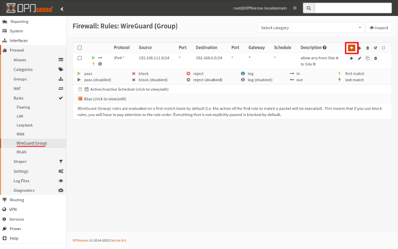
To add a rule that explicitly allows this, navigate to the Firewall > Rules > WireGuard page. Click the Add icon on it:
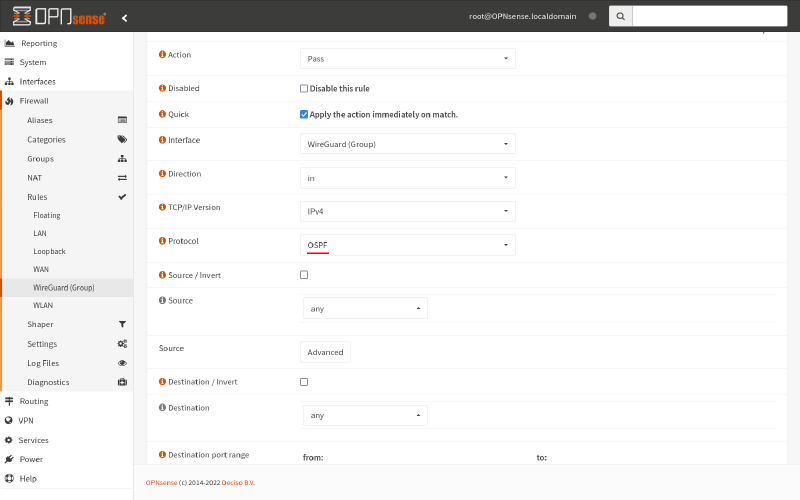
Set the Protocol to OSPF; then click the Save button:
You may also want to relax some of your firewall restrictions to allow for new networks to be added dynamically at Site A. For this example scenario, we’ll relax our restrictive firewall rules from the original OPNsense WireGuard Site-to-Site guide, and just use a single firewall rule that accepts any packets received through the WireGuard interface:
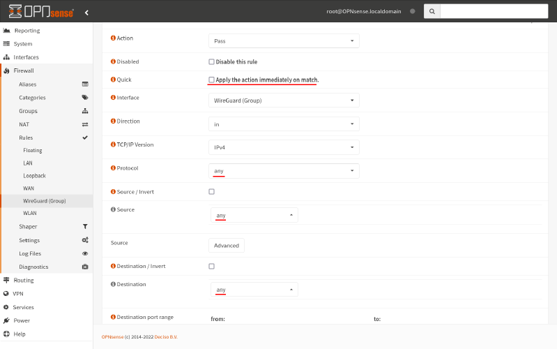
This rule is basically equivalent to the iifname $wg_iface accept nftables rule from above (if applied to both the input and forward chains).
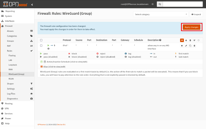
After making changes, be sure to click the Apply Changes button to apply your changes:
Define WireGuard Interface on OPNsense
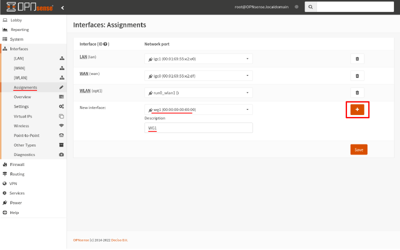
One more thing we need to adjust on Router B is we need to set up an explicit interface assignment for our WireGuard interface (so that we can configure OSPF for it later, in the Configure OSPF Interfaces on OPNsense step).
To do so, navigate to the Interfaces > Assignments page. In the New interface section, select the wg1 interface, and give it a Description of WG1. Then click the Add icon:
Next, navigate to the newly generated Interfaces > [WG1] page. Check the Enable Interface checkbox, which will reveal some further interface options:
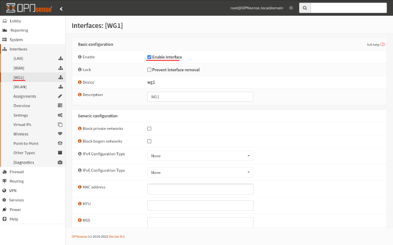
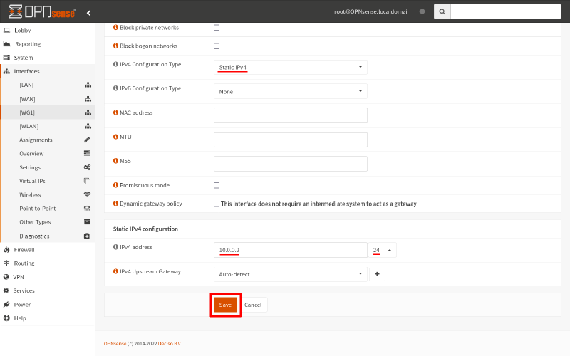
For the IPv4 Configuration Type field, select Static IPv4. For the IPv4 address field, enter 10.0.0.2/24 (matching the interface address and subnet we set up in the Adjust WireGuard Routes on OPNsense section above). Then click the Save button:
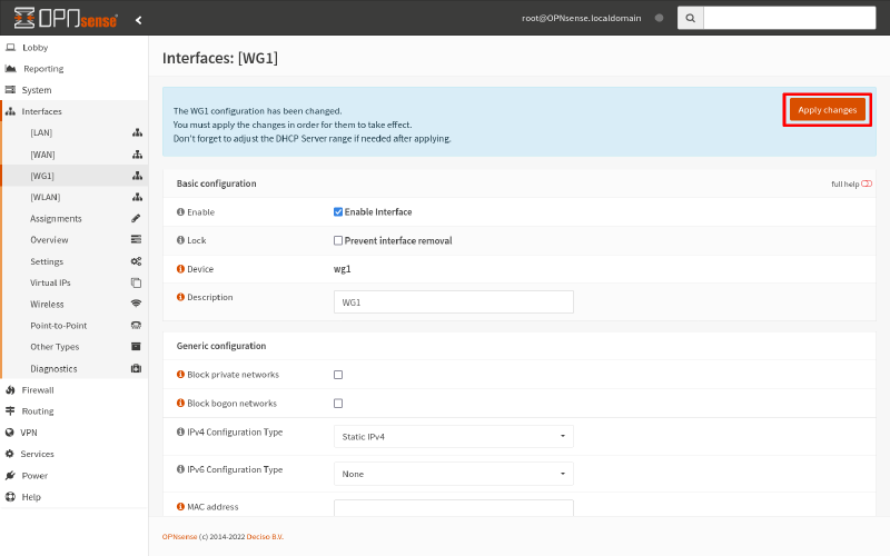
Finally, click the Apply changes button to apply this new interface definition:
Install FRR on Linux
Now we’re ready for OSPF. On Router A, install your OS (Operating System) frr package, or follow the Installation instructions from the FRR docs.
Install FRR on OPNsense
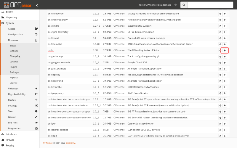
To install FRR on Router B, navigate to the System > Firmware > Plugins page. Search for the os-frr package in the plugins list, and click the Add icon for it:
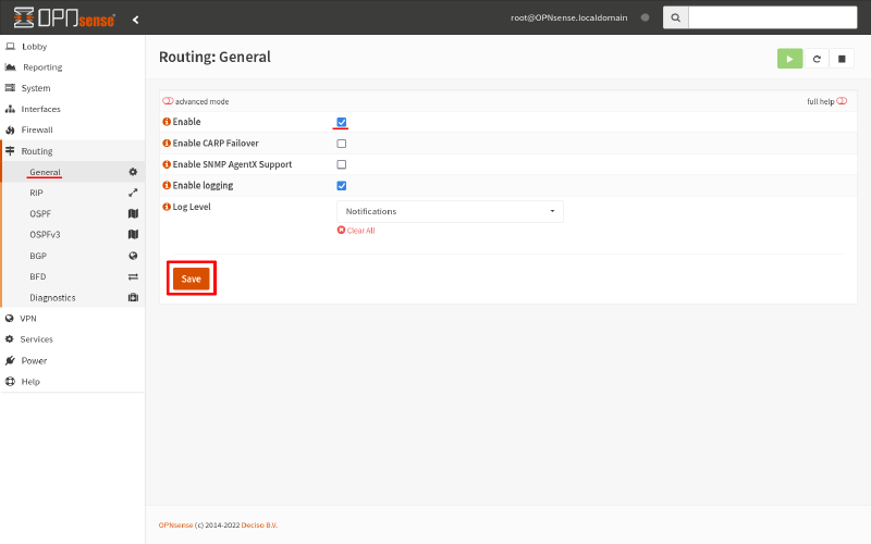
Then navigate to Routing > General page. Select the Enable checkbox, and click the Save button:
Start OSPF on Linux
To start up the OSPF daemon on Router A, edit the /etc/frr/daemons file, and change its ospfd property to yes:
ospfd=yesThen, if your FRR package set up an /etc/frr/frr.conf file (to use the “integrated” configuration mechanism), add the following content to the bottom of that file:
router ospf
 redistribute connected
 redistribute kernel
If your FRR package did not set up an /etc/frr/frr.conf file, instead create a new /etc/frr/ospfd.conf file, and add the above content to it instead.
This will set up FRR’s OSPF daemon, and enable it to share routes from the network interfaces on Router A, as well as any other routes in the kernel’s main routing table.
Restart FRR with this new configuration. If your FRR package set FRR up as a systemd service, run the following command to restart it:
$ sudo systemctl restart frrStart OSPF on OPNsense
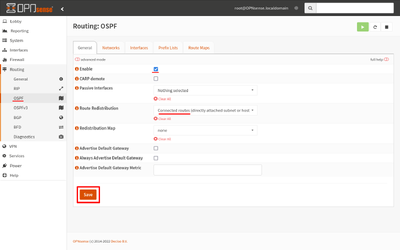
To start up OSPF on Router B, navigate to the Routing > OSPF page. Check the Enable checkbox. Then select the following options from the Route Redistribution field:
- Connected routes
-
Routes to the subnets of each of the router’s interfaces.
- Kernel routes
-
Any static routes you’ve set up via the System > Routes > Configuration page.
Then click the Save button:
Configure OSPF Interfaces on Linux
At this point, the OSPF daemon will be up and running on both routers, but neither are configured with an OSPF area in which to exchange routes.
On Router A, modify the /etc/frr/frr.conf file (with an integrated configuration) or the /etc/frr/ospfd.conf file (with a traditional configuration) to add the following interface section:
interface wg0
 ip ospf area 10.0.0.0
 ip ospf network point-to-point

router ospf
 redistribute connected
 redistribute kernel
This directs FRR to exchange routes with the OSPF area 10.0.0.0 through Router A’s WireGuard interface (wg0); and it informs FRR that the interface represents a point-to-point connection (as opposed to a normal broadcast connection).
If you have a sophisticated network, you might have several different OSPF areas, and use FRR’s access/prefix lists or route maps to fine-tune exactly which routes are shared among the various areas. But to get started with OSPF, this is all we need to share all the routes Router A knows about with Router B.
Reload FRR after updating the config file. If your FRR package set FRR up as a systemd service, run the following command to reload it:
$ sudo systemctl reload frrConfigure OSPF Interfaces on OPNsense
Now we need to configure Router B similarly to start exchanging routes with Router A.
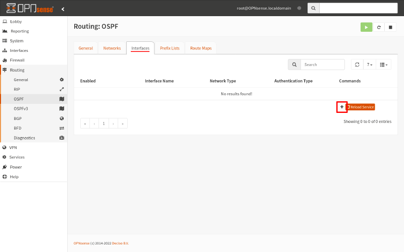
From the Routing > OSPF page, switch to the Interfaces tab. Click the Add icon:
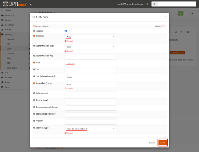
Configure the following settings in the Edit Interface dialog:
- Interface
-
Select the
WG1interface we set up in the Define WireGuard Interface on OPNsense section above. - Area
-
Enter
10.0.0.0, to match the OSPF area we used for the WireGuard interface on Router A. - Network Type
-
Select
Point-to-point network, to inform FRR that this interface is to simply a point-to-point link.
Then click the Save button:
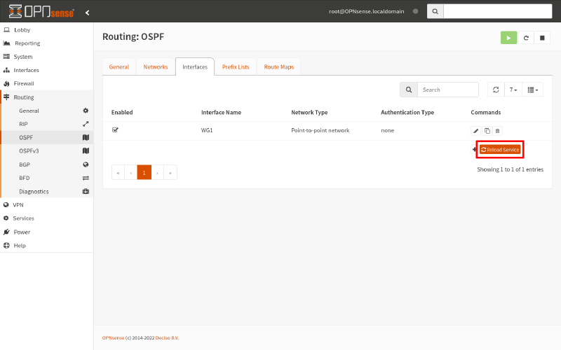
Finally, click the Reload Service button, to reload FRR on Router B with this updated configuration.
Test It Out
Router A and Router B should now be exchanging all the routes they know about with each other across their WireGuard interfaces — so routing between the two sites should be working as it did when we started. Just like with the original OPNsense WireGuard Site-to-Site guide, you should be able to use Endpoint A to access the webserver on Endpoint B using Endpoint B’s LAN address (192.168.200.22):
$ curl 192.168.200.22But now (as long as you don’t have any firewall restrictions between Site A and Site B, or you adjusted them to allow for additional subnets) if you add additional subnets on the Site A side, or the Site B side, or both, you don’t have to adjust your WireGuard AllowedIPs settings on the opposite site. You can simply add the subnet at one site, and allow that site’s router to share the new route to the subnet with the other site over OSPF.
For example, if we added a new subnet to Site A (192.168.111.0/24) and a new subnet to Site B (192.168.202.0/24), Endpoint AAA in Site A’s new subnet (192.168.111.123) would be able to access Endpoint BBB in Site B’s new subnet (192.168.202.234):

The tracepath from Endpoint AAA to Endpoint BBB might look something like this:
me@endpoint-aaa:~$ tracepath -n 192.168.202.234
 1?: [LOCALHOST]                      pmtu 1500
 1:  192.168.111.1                                         0.391ms
 2:  192.168.1.1                                           1.355ms
 3:  192.168.1.1                                           1.368ms pmtu 1420
 3:  10.0.0.2                                             19.441ms
 4:  192.168.200.2                                        22.479ms
 5:  192.168.202.234                                      22.840ms reached
     Resume: pmtu 1420 hops 5 back 5
Troubleshooting
The OPNsense GUI provides a helpful set of pages in the Routing > Diagnostics group. You can also use the VTY shell tool on both Linux and OPNsense. Start it up by running the vtysh command as root:
$ sudo vtysh
router-a# show daemons
 zebra ospfd watchfrr staticd
Neighbors
The first thing to check when troubleshooting OSPF is to verify that the router has found its neighbors. In the VTY shell, run the show ip ospf neighbor command. This is what you should see (on Router A):
router-a# show ip ospf neighbor

Neighbor ID     Pri State           Dead Time Address         Interface                        RXmtL RqstL DBsmL
192.168.200.1     1 Full/DROther      35.047s 10.0.0.2        wg0:10.0.0.1                         0     0     0
In the OPNsense GUI, navigate to the Routing > Diagnostics > OSPF page, and switch to the Neighbor tab. This is what you should see (on Router B):
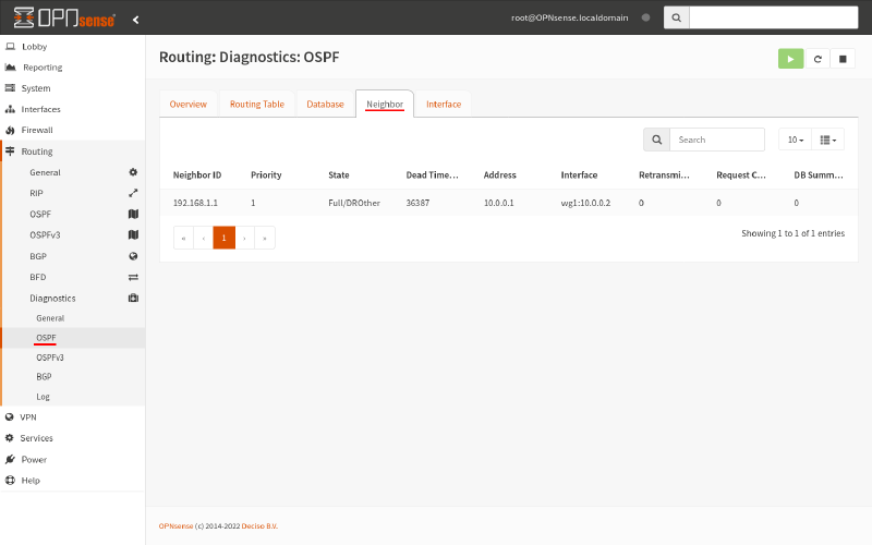
If one of the routers hasn’t found each other, check for these things:
Interface OSPF area matches
The WireGuard interface on Router A and Router B must both be in the same OSPF area. You can double check this by running the show ip ospf interface command in the VTY shell:
router-a# show ip ospf interface
wg0 is up
  ifindex 16, MTU 1420 bytes, BW 0 Mbit <UP,POINTOPOINT,RUNNING,NOARP>
  Internet Address 10.0.0.1/24, Broadcast 10.0.0.255, Area 10.0.0.0
  MTU mismatch detection: enabled
  Router ID 192.168.1.1, Network Type POINTOPOINT, Cost: 10
  Transmit Delay is 1 sec, State Point-To-Point, Priority 1
  No backup designated router on this network
  Multicast group memberships: OSPFAllRouters
  Timer intervals configured, Hello 10s, Dead 40s, Wait 40s, Retransmit 5
    Hello due in 7.284s
  Neighbor Count is 1, Adjacent neighbor count is 1
Or in the OPNsense GUI, navigate to the Routing > Diagnostics > OSPF page, and switch to the Interface tab:
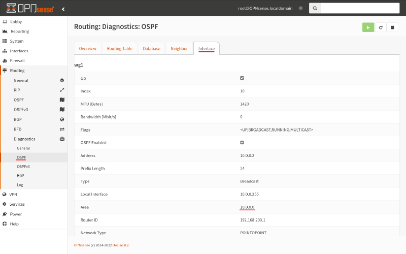
The area listed must be the same. In our example, it’s 10.0.0.0 (see the Configure OSPF Interfaces on Linux and OPNsense sections).
WireGuard tunnel is up
The WireGuard tunnel must be up and operational. To check this on Router A, run the wg command:
$ sudo wg
interface: wg0
  public key: /TOE4TKtAqVsePRVR+5AA43HkAK5DSntkOCO7nYq5xU=
  private key: (hidden)
  listening port: 51821

peer: fE/wdxzl0klVp/IR8UcaoGUMjqaWi3jAd7KzHKFS6Ds=
  endpoint: 203.0.113.2:51822
  allowed ips: 0.0.0.0/0
  latest handshake: 46 seconds ago
  transfer: 2.20 MiB received, 12.09 GiB sent
On Router B, navigate to the VPN > WireGuard page, and switch to the List Configuration tab:
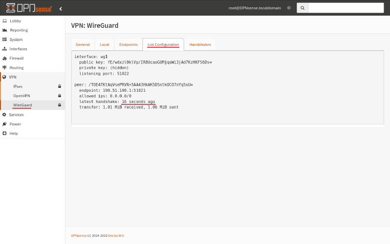
If you don’t see a recent handshake listed, your WireGuard tunnel is not operational. You need to fix your WireGuard or WAN firewall settings at one or both sites (see the original OPNsense WireGuard Site-to-Site guide for this).
Firewall allows OSPF packets
The firewalls on both Router A and Router B must allow OSPF packets in on their WireGuard interfaces. To check, run Tcpdump on each router’s WireGuard interface:
$ sudo tcpdump -ni wg0 proto ospf
23:05:02.847056 wg0   In  IP 10.0.0.2 > 224.0.0.5: OSPFv2, Hello, length 48
23:05:03.838379 wg0   Out IP 10.0.0.1 > 224.0.0.5: OSPFv2, Hello, length 48
23:05:03.838409 wg0   Out IP 10.0.0.1 > 224.0.0.5: OSPFv2, LS-Update, length 64
23:05:03.977641 wg0   In  IP 10.0.0.2 > 224.0.0.5: OSPFv2, LS-Ack, length 44
23:05:12.847067 wg0   In  IP 10.0.0.2 > 224.0.0.5: OSPFv2, Hello, length 48
23:05:13.838547 wg0   Out IP 10.0.0.1 > 224.0.0.5: OSPFv2, Hello, length 48
You should see regular “hello” packets being exchanged (if not, see the Adjust WireGuard Firewall on Linux and OPNsense sections).
Adjacency
If your routers have found each other as neighbors, the next thing to verify is that they’ve established adjacency with each other. In the VTY shell, run the show ip ospf interface command. This what you should see (on Router A):
router-a# show ip ospf interface
wg0 is up
  ifindex 16, MTU 1420 bytes, BW 0 Mbit <UP,POINTOPOINT,RUNNING,NOARP>
  Internet Address 10.0.0.1/24, Broadcast 10.0.0.255, Area 10.0.0.0
  MTU mismatch detection: enabled
  Router ID 192.168.1.1, Network Type POINTOPOINT, Cost: 10
  Transmit Delay is 1 sec, State Point-To-Point, Priority 1
  No backup designated router on this network
  Multicast group memberships: OSPFAllRouters
  Timer intervals configured, Hello 10s, Dead 40s, Wait 40s, Retransmit 5
    Hello due in 7.284s
  Neighbor Count is 1, Adjacent neighbor count is 1
Or in the OPNsense GUI, navigate to the Routing > Diagnostics > OSPF page, and switch to the Interface tab:
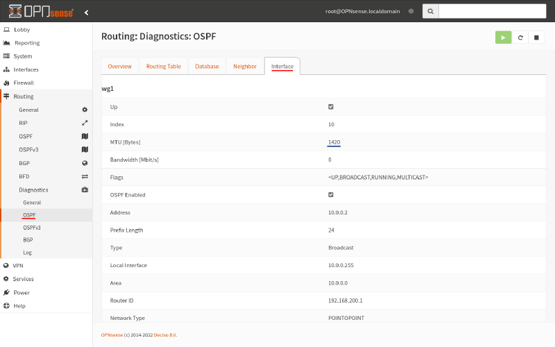
Then scroll to the bottom of the page:
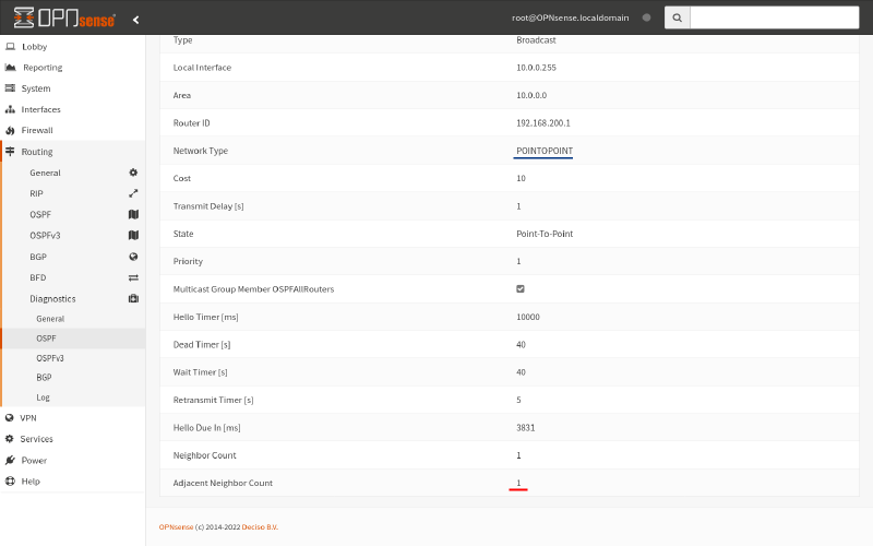
If their Adjacent Neighbor Count is not 1, check for these things:
Interfaces are point-to-point
The WireGuard interfaces on Router A and Route B must be registered as point-to-point with FRR. The Network Type in the displays above must show POINTTOPOINT for both routers. If not, you need to fix your OSPF interface definitions (see the Configure OSPF Interfaces on Linux and OPNsense sections).
Interface MTU matches
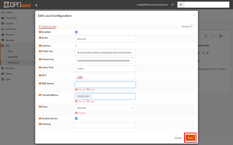
The WireGuard interfaces on Router A and Route B must also have a matching MTU. The MTU in the displays above must show the same value for both routers; in our example, the MTU for both is 1420 bytes.
If the MTU doesn’t match, change the MTU of the higher interface to match the lower. For example, if Router A’s MTU was 1420 and Router B’s MTU was 1414, we’d have to make the following change to the /etc/wireguard/wg0.conf file on Router A:
# /etc/wireguard/wg0.conf

# local settings for Router A
[Interface]
PrivateKey = AAAAAAAAAAAAAAAAAAAAAAAAAAAAAAAAAAAAAAAAAEE=
Address = 10.0.0.1/24
ListenPort = 51821
Table = off
MTU = 1414

# remote settings for Router B
[Peer]
PublicKey = fE/wdxzl0klVp/IR8UcaoGUMjqaWi3jAd7KzHKFS6Ds=
Endpoint = 203.0.113.2:51822
AllowedIPs = 0.0.0.0/0
Or if Router A’s MTU was 1380 and Router B’s MTU was 1420, we’d have to navigate to the VPN > WireGuard page of Router B, switch to the Local tab, and edit the configuration for the RouterB configuration like this (using the advanced mode toggle button to display the MTU field):
Routes
If the routers have found each other, and established adjacency, then you should see that they’ve exchanged information about link states and routes when your run the show ip ospf route command in the VTY shell (on Router A):
router-a# show ip ospf route
============ OSPF network routing table ============
N    10.0.0.0/24           [10] area: 10.0.0.0
                           directly attached to wg0

============ OSPF router routing table =============
R    192.168.200.1         [10] area: 10.0.0.0, ASBR
                           via 10.0.0.2, wg0

============ OSPF external routing table ===========
N E2 192.168.200.0/24      [10/20] tag: 0
                           via 10.0.0.2, wg0
N E2 203.0.113.0/24        [10/20] tag: 0
                           via 10.0.0.2, wg0
And you should see a similar display in the OPNsense GUI (for Router B), when you navigate to the Routing > Diagnostics > OSPF page, and switch to the Routing Table tab:
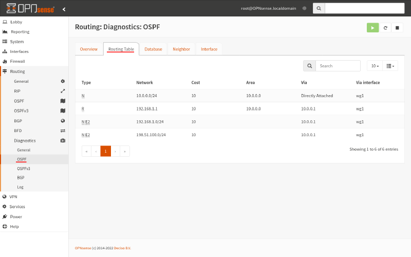
Also, you should see this when your run the show ip ospf database command in the VTY shell (on Router A):
router-a# show ip ospf database

       OSPF Router with ID (192.168.1.1)

                Router Link States (Area 10.0.0.0)

Link ID         ADV Router      Age  Seq#       CkSum  Link count
192.168.1.1    192.168.1.1     1375 0x8000004d 0x6a59 2
192.168.200.1  192.168.200.1   1375 0x8000003f 0x8286 2

                AS External Link States

Link ID         ADV Router      Age  Seq#       CkSum  Route
192.168.1.0    192.168.1.1      386 0x8000002b 0x3ada E2 192.168.1.0/24 [0x0]
192.168.200.0  192.168.200.1    425 0x80000008 0x5cbe E2 192.168.200.0/24 [0x0]
198.51.100.0   192.168.1.1     1296 0x8000002b 0xc28d E2 198.51.100.0/24 [0x0]
203.0.113.0    192.168.200.1   1126 0x80000030 0x01f0 E2 203.113.0/24 [0x0]
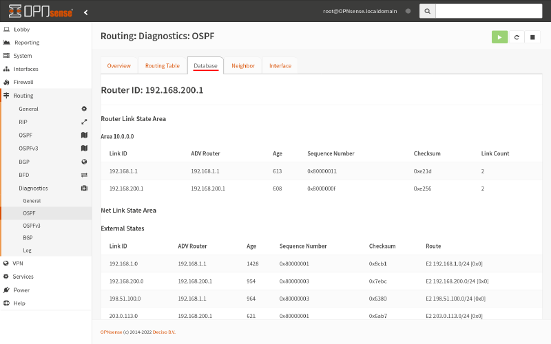
And you should see a similar display (for Router B), when you switch to the Database tab of the Routing > Diagnostics > OSPF page:
